

All its been 9 long months since this catastrophe happened, so I thought I would give a follow up.
Once I was able to get the knee gib removed, I thought that it was about time to put wheels on the mill and during this process I discovered that the rear of the casting was cracked in the same general location on each side. After pondering this for sometime the friend that helped me remove the gib had a friend that contracts with the city to perform magnaflux inspections and he kindly offered to magnaflux the areas in question for free.
Following his detailed inspection we were able to locate the ends of the cracks and I then drilled a .25" pilot hole followed by a .5" through holes at the ends of the cracks.
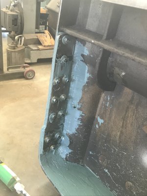
Not one to let a simple repair remain simple I decided to install 2 - .375" thick 1018 hr plates on the inside of the casting to span the cracked areas.
I drilled 11 - 5/16 holes in each plate. Clamped the plates in place and proceeded to use the plates as a drill jig to drill the casting for 3/16 allen set screws. I through tapped the casting which ranged from 1/2 to 5/8 thick, thoroughly cleaned and rough ground the inside of the casting and applied a structural epoxy to bed the plate and installed the fasteners but leaving then shy of the outer face by an 1/8". The outer face of the tapped holes and the hole that was drilled for the removal of the gib were patched with loctite steel epoxy and ground smooth.
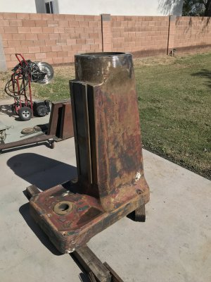
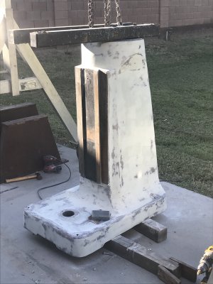
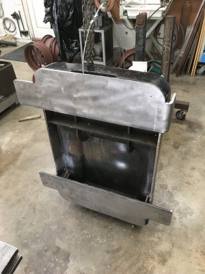
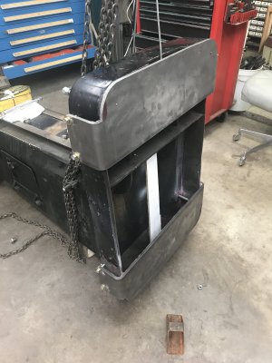
Following this work I decided that the base casting needed to be repainted and the nicks in the filler material smoothed out with new body filler. Unfortunately no matter how many times I washed the the casting with acetone or lacquer thinner the new filler would not stick as the old filler seemed to be oil soaked. Again a simple task becomes more complicated, I had to completely strip off all of the filler using 3M clean and strip wheels on my 7" side grinder. After a through cleaning I reapplied new filler and sanded the casing smooth. Applied 2 coats of PPG epoxy primer and top coated with PPG Urethane enamel.
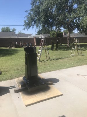
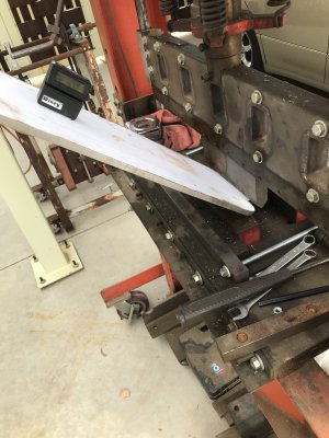
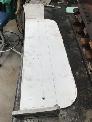
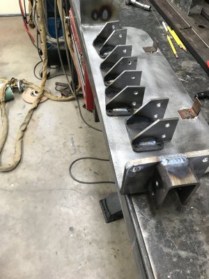
For the wheel assemblies I cut 2 pieces of 3/8 HR plate to fit the contour of the base casting and bent the side support wings in my press break.
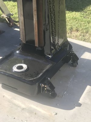
I drilled the base plates to mirror the location of the base casting mounting holes as these will later be tapped to 1/2-13 and used for jacking screws with swivel feet. I then proceeded to fab up the mounts for the 700 lb rated casters from 3/16 CR plate and tig welded the wheel mounts to the base plates, this assembly was then primed and panted at the same time as the base casting.
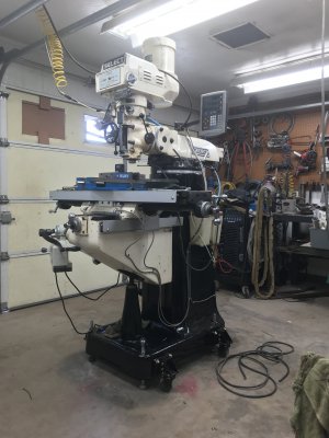
Finally the mill is assembled, the only open item is to fit up the limit switch for the powered z axis. And this takes me back to what started this project, lowering the knee to the maximum to set the lower limit but I'll be much more careful this time.
Thanks and keep your ways clean and lubed.
Once I was able to get the knee gib removed, I thought that it was about time to put wheels on the mill and during this process I discovered that the rear of the casting was cracked in the same general location on each side. After pondering this for sometime the friend that helped me remove the gib had a friend that contracts with the city to perform magnaflux inspections and he kindly offered to magnaflux the areas in question for free.
Following his detailed inspection we were able to locate the ends of the cracks and I then drilled a .25" pilot hole followed by a .5" through holes at the ends of the cracks.
Not one to let a simple repair remain simple I decided to install 2 - .375" thick 1018 hr plates on the inside of the casting to span the cracked areas.
I drilled 11 - 5/16 holes in each plate. Clamped the plates in place and proceeded to use the plates as a drill jig to drill the casting for 3/16 allen set screws. I through tapped the casting which ranged from 1/2 to 5/8 thick, thoroughly cleaned and rough ground the inside of the casting and applied a structural epoxy to bed the plate and installed the fasteners but leaving then shy of the outer face by an 1/8". The outer face of the tapped holes and the hole that was drilled for the removal of the gib were patched with loctite steel epoxy and ground smooth.
Following this work I decided that the base casting needed to be repainted and the nicks in the filler material smoothed out with new body filler. Unfortunately no matter how many times I washed the the casting with acetone or lacquer thinner the new filler would not stick as the old filler seemed to be oil soaked. Again a simple task becomes more complicated, I had to completely strip off all of the filler using 3M clean and strip wheels on my 7" side grinder. After a through cleaning I reapplied new filler and sanded the casing smooth. Applied 2 coats of PPG epoxy primer and top coated with PPG Urethane enamel.
For the wheel assemblies I cut 2 pieces of 3/8 HR plate to fit the contour of the base casting and bent the side support wings in my press break.
I drilled the base plates to mirror the location of the base casting mounting holes as these will later be tapped to 1/2-13 and used for jacking screws with swivel feet. I then proceeded to fab up the mounts for the 700 lb rated casters from 3/16 CR plate and tig welded the wheel mounts to the base plates, this assembly was then primed and panted at the same time as the base casting.
Finally the mill is assembled, the only open item is to fit up the limit switch for the powered z axis. And this takes me back to what started this project, lowering the knee to the maximum to set the lower limit but I'll be much more careful this time.
Thanks and keep your ways clean and lubed.
Attachments
-
 IMG_2312.JPG1.6 MB · Views: 19
 -
 IMG_2325.JPG2.2 MB · Views: 15
 -
 IMG_2429.JPG1.3 MB · Views: 14
 -
 IMG_2432.JPG2.1 MB · Views: 13
 -
 IMG_2014.JPG1.8 MB · Views: 13
 -
 IMG_2009.JPG1.6 MB · Views: 13
 -
 IMG_2016.JPG1.6 MB · Views: 13
 -
 IMG_2274.JPG1.7 MB · Views: 13
 -
 IMG_2323.JPG1.8 MB · Views: 12
 -
 IMG_2433.JPG1.2 MB · Views: 15
 -
 IMG_2667.JPG1.4 MB · Views: 18