- Joined
- May 23, 2020
- Messages
- 15
Several years ago I acquired a lightly used Syil X6 CNC Mill at an auction. These machines aren't known for their high reliability, but for my simple little projects, it has generally served me well. However, recently the spindle drive started acting up. The machine uses a 1.5kW (~2HP) brushless DC motor with a hall effect sensor, and the thing would randomly slow down during a cut. At first, it only happened during turns, so I wrote it off, but then it started occurring mid cut as well. As expected, this resulted in a broken end mill...
After a few internet search showing this problem wasn't uncommon for that machine, and a call to Syil confirming the units were no longer in production, I decided the best option was to forego the BLDC motor in favor of a 3-phase motor and a VFD. I do recognize you can by low cost BLDC drivers on Alibaba and such, but I didn't really feel like messing with one, and the name brand DC drives I found were more expensive than going 3-phase. A las, the conversion begins!
The original motor is small diameter and uses a flange mount. My goal was to interface with the existing bolt pattern, as there isn't much meat on the casting head to move the pattern outboard. The Syil's have a silly sheet metal cover around the head that I pulled off which removed around 10 lbs, and compensated for the increased motor weight.
I went through a few iterations of brackets to play around with tooling clearance, and eventually settled on something similar to the one below. There was one final iteration which is why it changes color when mounted on the mill...

The holes are countersunk and interface with the face mount on the motor.

I changed from socket head cap screws to studs on the interface to the mill head. I also used 12 point nuts because it allowed me to use a 10 mm wrench instead of a 13 mm so tool clearance was less of an issue. As you can see in the first picture, some of the wall thicknesses get pretty tight near the through holes. The overhang on the edge is the same as with the original bracket mount.

Next was tensioning the belt. I don't have a tension meter, so I rigged something up with an indicator and a fish scale. A little clumsy to install, but easy to use once it was setup.


I don't have an exact tension requirement in the manual, but after looking through the Misumi catalogues, I decided 4.5 lbf was probably in the ballpark at a deflection of 0.0625".
Now, obviously I don't intend to use the 3D printed bracket long term (3D printing was more for fit checks), but I couldn't resist the urge to fire up the spindle! The end result was the thing is fairly noise. It wasn't quiet before I started the conversion, but nonetheless, I started poking around for ideas on what could be causing it.
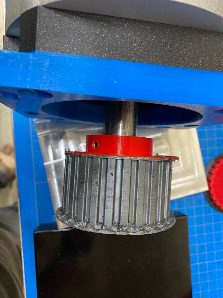
I played with belt tension, but regardless of what I did, I couldn't get the thing to stay quiet above ~2000 RPM's, so I started poking around with an indicator... I knew I had a touch of runout on the motor pulley because when I bored it out for the new motor shaft, I got overzealous, but only to the tune of ~0.003 of run out on the bore relative to the collar. I don't have a picture of the pulley, but I'll grab one after the next disassembly. When boring it, I didn't have a way to check it relative to the teeth, but I figured now that it's installed, I can look at the run out on the belt, it came in at 0.050! In contrast, the run out on the pulley on the spindle is ~0.010 (also not great, but definitely better).
Next step will be pulling it apart and trying to figure out how to get a sleeve in there to align the pulley with the central bore. Or, perhaps it might be easier to just replace the entire pulley... more to come as the project continues.
After a few internet search showing this problem wasn't uncommon for that machine, and a call to Syil confirming the units were no longer in production, I decided the best option was to forego the BLDC motor in favor of a 3-phase motor and a VFD. I do recognize you can by low cost BLDC drivers on Alibaba and such, but I didn't really feel like messing with one, and the name brand DC drives I found were more expensive than going 3-phase. A las, the conversion begins!
The original motor is small diameter and uses a flange mount. My goal was to interface with the existing bolt pattern, as there isn't much meat on the casting head to move the pattern outboard. The Syil's have a silly sheet metal cover around the head that I pulled off which removed around 10 lbs, and compensated for the increased motor weight.
I went through a few iterations of brackets to play around with tooling clearance, and eventually settled on something similar to the one below. There was one final iteration which is why it changes color when mounted on the mill...
The holes are countersunk and interface with the face mount on the motor.
I changed from socket head cap screws to studs on the interface to the mill head. I also used 12 point nuts because it allowed me to use a 10 mm wrench instead of a 13 mm so tool clearance was less of an issue. As you can see in the first picture, some of the wall thicknesses get pretty tight near the through holes. The overhang on the edge is the same as with the original bracket mount.
Next was tensioning the belt. I don't have a tension meter, so I rigged something up with an indicator and a fish scale. A little clumsy to install, but easy to use once it was setup.
I don't have an exact tension requirement in the manual, but after looking through the Misumi catalogues, I decided 4.5 lbf was probably in the ballpark at a deflection of 0.0625".
Now, obviously I don't intend to use the 3D printed bracket long term (3D printing was more for fit checks), but I couldn't resist the urge to fire up the spindle! The end result was the thing is fairly noise. It wasn't quiet before I started the conversion, but nonetheless, I started poking around for ideas on what could be causing it.
I played with belt tension, but regardless of what I did, I couldn't get the thing to stay quiet above ~2000 RPM's, so I started poking around with an indicator... I knew I had a touch of runout on the motor pulley because when I bored it out for the new motor shaft, I got overzealous, but only to the tune of ~0.003 of run out on the bore relative to the collar. I don't have a picture of the pulley, but I'll grab one after the next disassembly. When boring it, I didn't have a way to check it relative to the teeth, but I figured now that it's installed, I can look at the run out on the belt, it came in at 0.050! In contrast, the run out on the pulley on the spindle is ~0.010 (also not great, but definitely better).
Next step will be pulling it apart and trying to figure out how to get a sleeve in there to align the pulley with the central bore. Or, perhaps it might be easier to just replace the entire pulley... more to come as the project continues.