-
Welcome back Guest! Did you know you can mentor other members here at H-M? If not, please check out our Relaunch of Hobby Machinist Mentoring Program!
You are using an out of date browser. It may not display this or other websites correctly.
You should upgrade or use an alternative browser.
You should upgrade or use an alternative browser.
VN Taking apart a Van Norman #2 head.
- Thread starter herbet999
- Start date
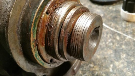
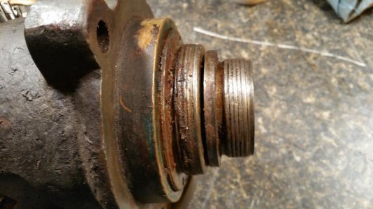
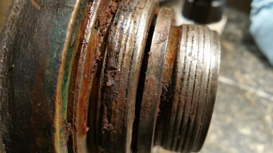
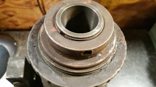
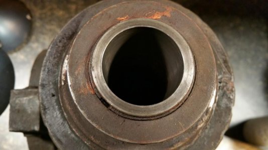
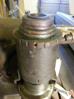
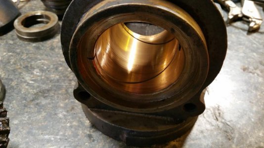
Made some progress this morning... before eating turkey. I've removed the bearing stops on the back (top) of the head. I'm stuck now. I don't see how to remove any more items. I may be at a point where I have to press out the spindle, although I wouldn't know what direction to go. Front to back or vice versa. I thought that the piece behind the two bearing stops would come off but I don't see anyway of getting it off and it's not coming off by itself. If you look in the last picture.. there is a brass looking ring directly inside the outer threads of the head casting. This brass part does not spin when you spin the spindle, but the steel bearing cover (that's what I'm calling it) does spin.
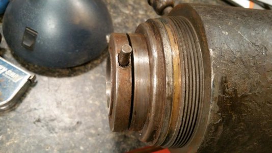
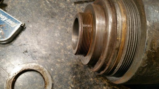
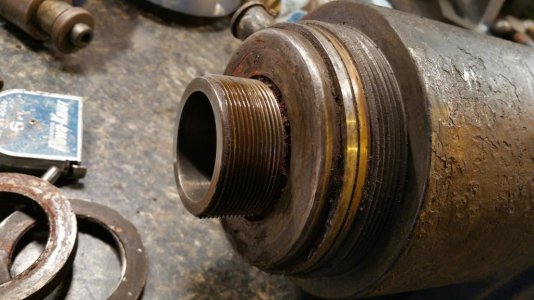


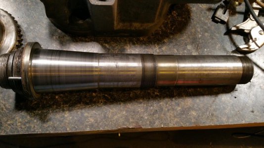
I was able to press the spindle out of the head. Actually with very little pressure. I don't know why I was expecting bearings but it turns out it has brass sleeve bushings and not bearings. Anyway, it's all back to together and now is very smooth. The bushings weren't in perfect condition but I think it's good enough for the minimal work I'll be using the mill for. I tried to press the "c" type adapter out the spindle but it would not budge and I was afraid to put too much pressure on it using my press. So I decided to leave it alone.


Last edited:
- Joined
- Sep 3, 2011
- Messages
- 478
Thanks for that, Bob. Lots of useful stuff there.
Note however that Joe's machine is a No. 2 Duplex milling machine. The No. 2 manual on the site is for a No. 2 horizontal milling machine, which came much later. Joe's machine is a lot closer to the No. 10 duplex milling machine.
Cal
- Joined
- Sep 3, 2011
- Messages
- 478
I was able to press the spindle out of the head. Actually with very little pressure. I don't know why I was expecting bearings but it turns out it has brass sleeve bushings and not bearings. Anyway, it's all back to together and now is very smooth. The bushings weren't in perfect condition but I think it's good enough for the minimal work I'll be using the mill for. I tried to press the "c" type adapter out the spindle but it would not budge and I was afraid to put too much pressure on it using my press. So I decided to leave it alone.
View attachment 88642
View attachment 88643
Hi Joe,
I managed to sneak away for a week over Thanksgiving. I'm glad to see that you were able to get the head apart and back together.
How is does the ring-gear drive the spindle? (I don't see a keyway in the spindle.) I'm very curious about the details of how the ring-gear is adjusted and held in place. Do you have any photos? How did you adjust the backlash of the ring-gear when you put it back?
What you have are plain bearings (as opposed to ball or roller bearings) and I would guess that they are made of some sort of bronze. What are you using for grease? You need to be careful about what grease you use, because a typical EP (extreme pressure) automotive grease has additives that can attack alloys like bronze that contain copper. Some information on grease can be found here:
http://wiki.vintagemachinery.org/Greases and Lubrication.ashx
The front bearing is tapered so that you can take out the play by tightening the rear collar. If the rear bearing gets too loose, you can bore the bearing sleeve out with a suitable boring bar, held between centers. Then a new bearing sleeve is pressed in and bored/honed to size. I would probably send that sort of work out to a shop that specializes in that sort of thing rather than try it myself.
As far as the C adapter in the spindle is concerned, it's probably cemented into the spindle by rust and dried lubricants. Penetrating oil (a 50:50 mix of acetone and automatic transmission fluid works very well), heat and patience are your main tools. Tapers seem to come out more easily if you can pull on the large end rather than push on the small end. It might be possible to make up a pair of wedges to fit between the lip on the adapter and the nose of the spindle, similar to a pair of jacobs taper removal wedges. If you can clean up the threads on the adapter you could make up a nut that you could tighten against the nose of the spindle to pull the adapter out. Be prepared to spend multiple sessions applying penetrating oil and tightening the puller, perhaps heating the spindle with a heat gun, and taping on the back of the adapter with a soft-faced drift. If you keep doing that day after day, a few minutes a day, it will eventually release.
Cal
Grats on tackling that machine Cal. Glad it helped :}
Thanks for that, Bob. Lots of useful stuff there.
Note however that Joe's machine is a No. 2 Duplex milling machine. The No. 2 manual on the site is for a No. 2 horizontal milling machine, which came much later. Joe's machine is a lot closer to the No. 10 duplex milling machine.
Cal
Hi Joe,
I managed to sneak away for a week over Thanksgiving. I'm glad to see that you were able to get the head apart and back together.
How is does the ring-gear drive the spindle? (I don't see a keyway in the spindle.) I'm very curious about the details of how the ring-gear is adjusted and held in place. Do you have any photos? How did you adjust the backlash of the ring-gear when you put it back?
What you have are plain bearings (as opposed to ball or roller bearings) and I would guess that they are made of some sort of bronze. What are you using for grease? You need to be careful about what grease you use, because a typical EP (extreme pressure) automotive grease has additives that can attack alloys like bronze that contain copper. Some information on grease can be found here:
http://wiki.vintagemachinery.org/Greases and Lubrication.ashx
The front bearing is tapered so that you can take out the play by tightening the rear collar. If the rear bearing gets too loose, you can bore the bearing sleeve out with a suitable boring bar, held between centers. Then a new bearing sleeve is pressed in and bored/honed to size. I would probably send that sort of work out to a shop that specializes in that sort of thing rather than try it myself.
As far as the C adapter in the spindle is concerned, it's probably cemented into the spindle by rust and dried lubricants. Penetrating oil (a 50:50 mix of acetone and automatic transmission fluid works very well), heat and patience are your main tools. Tapers seem to come out more easily if you can pull on the large end rather than push on the small end. It might be possible to make up a pair of wedges to fit between the lip on the adapter and the nose of the spindle, similar to a pair of jacobs taper removal wedges. If you can clean up the threads on the adapter you could make up a nut that you could tighten against the nose of the spindle to pull the adapter out. Be prepared to spend multiple sessions applying penetrating oil and tightening the puller, perhaps heating the spindle with a heat gun, and taping on the back of the adapter with a soft-faced drift. If you keep doing that day after day, a few minutes a day, it will eventually release.
Cal
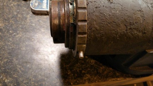
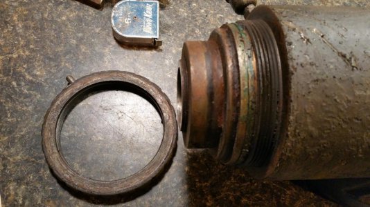
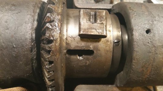
Cal, Here is a pic of the ring gear and the key way. The ring gear is held in place (against the force of the pinion gear) by a threaded ring. In the picture, the ring is to the right of the ring gear and still has the set screw in it. I made all adjustments really by doing careful measurements and making markings before taking anything apart. Then I simply restored everything back to the same position.
I did not grease the bushings I only oiled them with a naphthenic oil. There are also oiling fixtures on the head for both the top and bottom bushings. I did use bearing grease on the ring and pinion gears.

Last edited:
- Joined
- Sep 3, 2011
- Messages
- 478
Hi Joe,Cal, Here is a pic of the ring gear and the key way. The ring gear is held in place (against the force of the pinion gear) by a threaded ring. In the picture, the ring is to the right of the ring gear and still has the set screw in it. I made all adjustments really by doing careful measurements and making markings before taking anything apart. Then I simply restored everything back to the same position.
I did not grease the bushings I only oiled them with a naphthenic oil. There are also oiling fixtures on the head for both the top and bottom bushings. I did use bearing grease on the ring and pinion gears.
View attachment 89108
OK, so there's nothing to keep the ring gear from moving forward, apart from the pinion gear? All the No. 12 cutter-heads have some method of locking the ring gear in place; the exact method changed with the various versions of the head.
I wasn't looking carefully at the oil cups on your head. The older No. 12 heads use a similar looking grease fitting where you screwed the cap in a bit at a time to force grease into the bearing. It's interesting how they installed the oil cups at an angle so that the oil could gravity feed when the head is in the vertical position. Did you find felt in the oil cups?
On a spindle like this, it's always a good idea to put witness marks on the lock ring and pinion gear and count the number of exposed threads on the spindle so that you can get the ring back to the original position. IIRC, you should have about 10 degrees of backlash on the ring gear; you don't what it running with no lash.
Do you have the cover for the ring gear?
Cal


