Taking up backlash on J&S surface grinder

Saxguy

Registered
Registered
Joined
Mar 2, 2017
Messages
76
I have a J&S 540p surface grinder, which has about a 1.5mm backlash on the front to rear (Y) axis.
Cant see any take-up options, and access to the screw/nut looks pretty difficult without a strip-down.
Anyone know about this particular fix on a J&S? Or, is this an acceptable amount of backlash, and is it just a matter of putting up with it?
Thanks
 
I can only really comment on my Harig grinder. Having less than an 1/8 turn of backlash makes the whole usage more present. Less forward back motions of that hand wheel. If you're primary or only doing flat surfaces to regrind flat then I would say learn to live with it. Otherwise if you are tool making an need to take few thou of the wall or bottom of a slot and you are reaching your head inside to see a light gap before wheel contact, yes then your machine needs new screws and nuts. There is so much to keep in your head when doing that, that remembering if you are on the push side or the pull side of a long gap is a lot to handle.

-Edit, correct spelling
 
Last edited:
If you learn to live with back lash it makes little difference. It is the machinist not the machine that makes the part
 
If you learn to live with back lash it makes little difference. It is the machinist not the machine that makes the part
I understand that, and I have owned a fair few machines with backlash. Some I lived with and some I dealt to. I would however, like to fix this one. I took the wheel assembly apart today to clean out the old grease (it was causing issues with auto-Y travel). I noticed that you could pull the wheel (the screw) forward about 3mm. The lash is just too much I feel.
 
I’m thinking that maybe there is a better way of taking the backlash out of my J&S 540P (Y axis). Just thought I might throw it out there and see what the clever folk think.

Gaining access to the existing nut looks a PITA. Oil tray/pump and hydraulic piping all need removing it seems (bugger!) to gain access.

Anyway, I withdrew the screw after removing the front handle/dial/ratchet/cam assembly. I haven’t measured it yet, but I think I can see a slight narrowing of the thread across most of the middle section, but the brass nut will have taken the majority of wear obviously.

First I was thinking, maybe I could just replace the brass nut (or at least bore it out and fit new threaded plug). But then I know its only doing half a job, and I wouldn’t sleep at night!

I could have a go at making the whole thing myself, but then it might be a little to difficult for my humble skillset.


The second option is, a ball screw assembly. But I haven’t had dealings with these yet, and not sure if the right pitch could be found (it would need small bearings looking at the existing thread, which again, I have yet to measure).


As for buy new and replace, well they are just too expensive I’m afraid.


Which ever way I go I will take some pics, and will be happy to post here. Maybe it will help someone else with similar predicament.


Thanks
 
Last edited:
Usually on a late model well built machine there are provisions in the nut to take up the backlash. Two Piece unit. My Boyer has about a quarter turn. I live with it for now just gotta pay attention to the dials. Thought of putting a DRO on it to help.
 
Usually on a late model well built machine there are provisions in the nut to take up the backlash. Two Piece unit. My Boyer has about a quarter turn. I live with it for now just gotta pay attention to the dials. Thought of putting a DRO on it to help.
Yeah, I have machines that have split nuts, but I think this one is just a simple bronze nut (looking at the replacement ones I have seen available). DRO, overkill I think for now, cost etc....
 
I had this same issue with the Reid grinder I bought. It had a lot of backlash on it. I made a new acme threaded shaft and nut. Didn't have much choice on this old machine.
I bored the bronze shaft and made a left hand threaded insert so I didn't have to replace the whole thing.
Joe
 

Attachments

  • Screenshot_20211223-170819_Gallery.jpg
    Screenshot_20211223-170819_Gallery.jpg
    37.3 KB · Views: 102
  • 20200222_150229.jpg
    20200222_150229.jpg
    67.5 KB · Views: 105
  • 20200222_161138.jpg
    20200222_161138.jpg
    62.4 KB · Views: 112
  • 20200222_161223.jpg
    20200222_161223.jpg
    53.9 KB · Views: 112
Hello, Saxguy :)

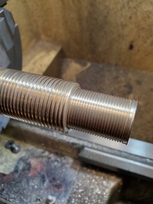
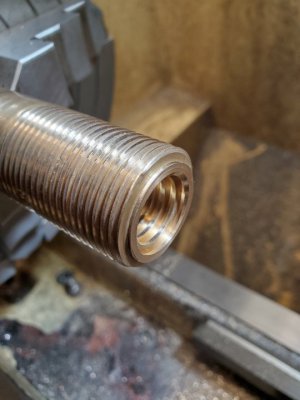
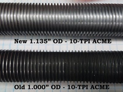
I just dealt with the same issue on my DoAll DH-612 manual surface grinder, mine had roughly .075" worth of backlash (1.9mm) which is right at 3/4 of a turn of the handwheel. Mine is 10TPI or .100" per revolution (2.54mm per revolution), when I took it apart I noticed that the thread thickness on the lead screw was only about .025" thick on the screw and in the nut (roughly .6mm).
I made the mistake of putting my finger inside the nut and I cut my finger slightly because the threads were so sharp, you would think I would have known better than to do that!! Lol

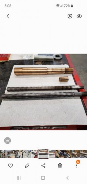
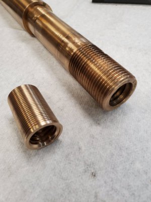
Anyway, there are no replacement parts for mine since DoAll quit making them and there are no aftermarket parts that I'm aware of so I had to make a new lead screw out of 4140.
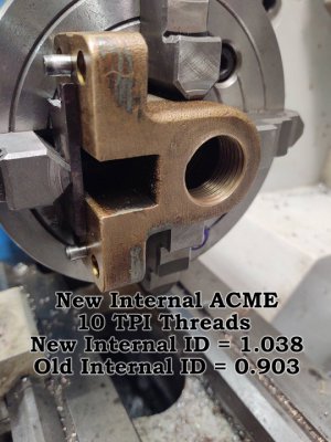
Instead of making a threaded bushing for the nut, I decided to make the lead screw about .135" larger, there was plenty of bronze left on the nut for a larger diameter lead screw and nothing else restricted me from doing that.
I had to take mine apart to rework the ways and the oiling system anyway, fortunately, mine is much less complex than yours!
Nice looking grinder BTW!!!

With your J&S, I would think that a minimal amount of backlash is a MUST since it has auto feed.
Mine is manual feed in all directions but 3/4 of a turn backlash was just too much! In fact, the X axis would completely quick working soon if I had left it alone.
I would think that a ball screw would be hard to keep from getting crunchy if even a slight amount of grinding swarf gets onto those balls (just a thought, I have very little experience with retrofitting surface grinders).
Grinding swarf is what caused all the damage on mine so my main goal now is to mitigate the grinding swarf by either adding a good vacuum system close to the wheel or maybe a better coolant recovery setup? Whatever it takes to keep that nasty swarf from eating up parts that are in contact with each other is the goal.

I don't plan to install a DRO as someone suggested, I use a test indicator on a mag base for sidewall grinding and that works pretty well for me.
Mine does have a gib lock on the X axis and that helps for sidewall grinding.

BTW, trying to take up backlash on worn lead screw threads doesn't usually work because the threads will bind when the lead screw moves into an area where the wear is less. If the only wear is in the nut, then it would work.

Questions:

1 - Do you have any repair manual drawings or a web link to a replacement lead screw and nut for your grinder?
2 - Is this the lead screw and nut that you need? https://www.andmar.co.uk/spares-82-saddle-cross-screw-and-nut
3 - Roughly how long is the lead screw is on yours?

4 - When you retract the lead screw to a portion where there is less wear, how much backlash do you observe?
The reason I ask is this: if there is very little backlash where there are less worn lead screw threads, that would mean that the nut has fairly good threads, if the backlash is only slightly less, then the threads in the nut are worn somewhat equally .
I've seen cases where the lead screw is softer than the bronze nut (Not hardened maybe or just soft steel?).
I plan to send y new one out to be hardened and tempered by a pro, if I do the hardening, it would probably wind up NOT straight anymore!! :-D

This hobby/business always has it's challenges and expenses!

Sorry for the long response, just trying to help if I can.
 

Attachments

  • Leadscrew Comparison - Old to New.jpg
    Leadscrew Comparison - Old to New.jpg
    149.4 KB · Views: 100
  • Nut in Lathe.jpg
    Nut in Lathe.jpg
    85.8 KB · Views: 102
I had this same issue with the Reid grinder I bought. It had a lot of backlash on it. I made a new acme threaded shaft and nut. Didn't have much choice on this old machine.
I bored the bronze shaft and made a left hand threaded insert so I didn't have to replace the whole thing.
Joe
Good solution and nicely done! :)
 
Back
Top