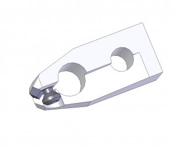
Tangential Tool Holder

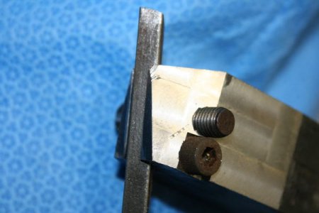
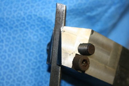
Implementing some changes. Tapping the second hole, 1/4 - 28.
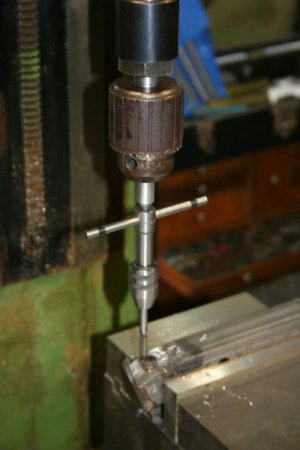
IMG_4346_zps6447a88a.jpg

A 1/4 - 28 bolt installed.
IMG_4347_zpsa89d5848.jpg

This is rough and being done mostly for my education. We grow too soon old and two late wise. I've decided to machine a bit holder in the opposite end of the steel, there is plenty of meat to do so. The cut from the side is very effective in relieving tension, it is very easy to trap the the bit by using very light tightening pressure on the 1/4" screw. You can see where the holder has rubbed, I don't know the best solution to this problem. Currently thinking it would be best to remove the offending metal on the vertical, rather than the horizontal surface.

Bob, your suggestion is excellent for those that have broaching capability. I do not. On the second attempt, I will make the hole .296". Make the longatudinal slit, with the cross slit about 1" behind the hole. This will remove tension, allow easy insertion of the forming bit and the press to do its thing. Will use two 5/16" clamping bolts, one top, one bottom. Milling will be a copy of this effort, unless Niel has some suggestions.

Bill
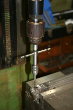
IMG_4346_zps6447a88a.jpg

IMG_4347_zpsa89d5848.jpg
 
Hello Bill

It is nice to see Your progress.
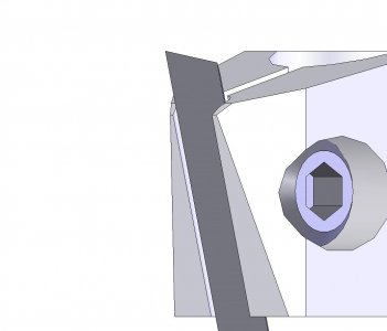
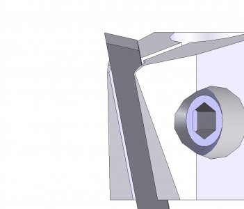
The rubbing clearance You mention is the only critical machining proces.Remove to little and tool do not function .Remove to much and the jaw will give after ten or twenty uses.The way I do it is not for the fainthearted.
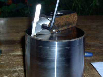
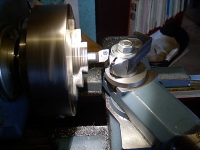
I grind a toolbit as I would for aluminium, that is a fore and aft rake of 20 to 25 degree and put it in working position in holder is as shown on photo.I put the combination onto compound slide but on a disc lifting it say 1/2 inch.The cutting edge is lined up with cutting plane of a one toth miller held in 3 jaw.Crosslide is advanced 0.3 mm against headstock and the miller does its work.I have only had one collisio but it sounded so awfull that I will disrecommend it to friends ans relatives.
A better way is to find a belt sander or disc sander and adjust table absolutely perpendicular to grinding surface.
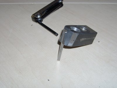
Take a toolbit and grind it as You would for aluminium and put it in holder in correct working position.
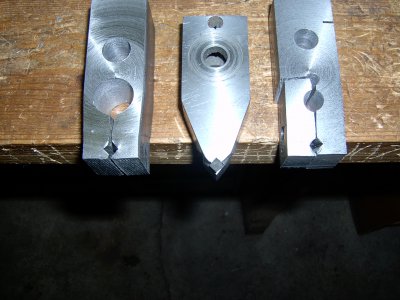
This will look somewhat like second picture.Carefully grind until block and tool looks like third picture.
For Your first tangential tool holder I will recomend that tool is tilted 15 degree fore and aft.!2 degree needs expirience.For 15 degree I will calculate tomorrow the ratio of grinded land width to wanted clearance.
Am to tired now

Regards

Niels

Tangential juster.jpg slibning1.jpg slibning.jpg
 
Have got back the spirit and want to try squeze manufacture once more

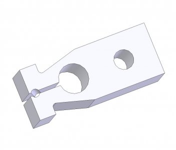
First operation is pure lathe,drilling and sawing.Looks kind of sharkey

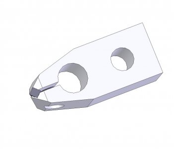
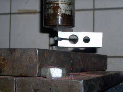
Next is squezing with undersize toolbit in place and 10 tons.Remove tooltoolbitt and free squeze until real toolbit just enters,Drill and cut thread for screw.
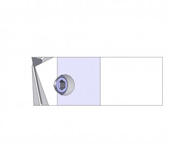
Saw the funny headpieces of and free grind or mill as described before

It will be better than first try.

fase 1.jpg fase 2.jpg side.jpg snit.jpg
 
Niels, I don't want to sound like the student lecturing the master, but I think weakening the entire holder enough to overcome the spring tension is not the way to go. You have weakened both sides of the holder, while if you saw in from the side and allow the steel to form a hinge, you have weakened only one side.

That said, I screwed up my second attempt. Seems I have trouble counting to ten. From the location of the hole that was drilled, I moved the talve 11 turns, which places the clamping screw .100" past the bit. A damn good arguement for DRO! So it looks like I'll try to clean up the original effort.

Bill
 
Hello Bill

It is nice knowing that I am not the only one that turn handles one turn to little or much.Screwing up .
Steel is cheap
You are rigth that I am weakening both sides,but think of the job as a roof spar:When tool is in and clamped it is part of a very stiff triangular construction that will move less for a given tool load than Your version.
We are not seeking strength,that is ability to survive obcene and deforming loads,but stiffness wich is minimizing deflection for a given load,far below levels where deformation plays a part.
I shall try and draw The two versions side by side but wife and dog demand newspaper fetching.
Kind regards

Niels
 
Hello Bill

I shall try and draw The two versions side by side but wife and dog demand newspaper fetching.
Kind regards

Niels

Isn't it great t o know you are needed?

Don't know exactly what I am doing or how to do it, but I was thinking more in terms of controlling vibration, which has moved me to give fleeting thought to material used for the holder. Specifically lead! That's the mentality your dealing with on this end.

Bill
 
Hello Bill

Have had some succes today

Made a 30 times 30 mm holder with a 20 mm hole for flexibilty.
Tool hole 6.7 mm (Diagonal of Crobalt 3/16). Angle 15 degree
Holding down hole 14 mm(My 14mm drill is sharp)

!4 tons pressure and looks quite good.
The best thing is that locking torque of clamping screw feels rigth.

It migth have been 19 or 18 mm but not less and I think this ratio of hole to width is universal.
The next one will start with 18 mm and be made bigger if to tough

Concerning material.I once worked with some ferritic stainles steel and after brazing it was dead as lead but much stronger of course.Will also look pretty.
Wife asks why I do not offer this squeze manufactured tangential tool to other hobby machinists.Main problem with this version is that first time a fellow amateur put in a round or underside tool bit in it is scrap.
If I had the drive to go comercial it would be the pull in version because a mm or two smallertoolbit does not harm to much

Kind regards

14 tons.JPG Efter.JPG
 
Niels, thanks for taking the time to write this up. I have been looking at TTH for a while and started building one a while back that I never have finished. Your design is much simpler and easier so I will be trying it as soon as I am feeling better.
 
Hello Joshua Hope You recover well because it is actually fun to make TT.

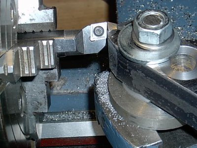
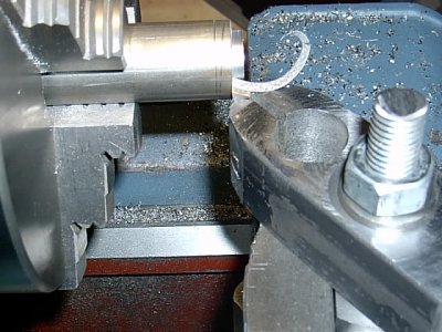
Three pictures

Milling in lathe very close and a little no no.
I ground a Crobalt as I would for alu (pointy I would say) and lowered point two mm from normal working position.
Lined the cutting edge paralel to 4 jaw body and milled as close as I dared.This gives around .3 mm clearance when working normally.

Last picture is cutting 3 mm deep.Quite fast and finest feed and remarkably good surface scrap shaft steel.

Do me a favour and make one Yourself and I have not lived in vain

My next will only have 18 mm flexhole.

Regards

IM000017.JPG IM000018.JPG IM000019.JPG
 
Last edited:
Back
Top