Taper attachment

Getting started with this project. The coupler nut arrived Friday while I was out of town. Today I found some aluminum and steel flat stock in my scrap bin. Any preference in using aluminum or steel for the end plate?
I have thought of another way to lock the shaft into the coupler nut. The coupler nut is 1/2 x 10 tpi LH acme. I thought about tapping half of the coupler nut with 1/2 x 13 RH standard thread. I would think that this would lock the coupler to the lead screw and the shaft when I tighten the shaft against the lead screw and having opposing threading would keep everything locked together. Is this a dumb idea?
I am still trying to figure out the math to calculate the diameter of the wheel. Info I found and posted above used a 10 tpi lead screw as an example but didn't include any of the actual math. The original article probably included the math. I have not found a copy online that I could study. The cross slide lead screw on my lathe is also 10 tpi. I have tried to back into his answer and the only thing I come up with is that he multiplied the taper per foot by 10. This seems too simplistic to me. I might have to make a wheel and measure how far the cross slide moves in one foot. Can anybody help me out with this?
 
Last edited:
Can anybody help me out with this?
I believe this is how I would calculate it, using 1/8" in/ft taper:
  • taper_ft (in_x/ft_z) = 0.125
  • lead screw pitch (turns_x/in_x)= 10
  • taper in inches (in_x/in_z) = taper_ft/12 = 0.01042
  • lead screw turns per carriage motion (turns_x/in_z) = pitch * taper = 0.1042
  • drive wheel circumference (in_z/turn_x) = 1 / (pitch * taper) = 9.6
  • drive wheel diameter (in) = 1 / (pi * pitch * taper) = 3.056"
I included some intermediate steps to hopefully explain better. The only thing, I think, is that the diameter calculated is the wheel plus one wire diameter. Happy to correct if I overlooked something. If I were you, I'd put it in a spreadsheet as I did.
 
Thanks so much for your analysis. I think that I have finally figured this out. This is how I understand how to calculate the diameter of the wheel in simpler terms
10 tpi makes 10 revolutions for every inch of travel. 1 revolution equals .1" of travel. 1/16" of travel equals .0625" or 62.5% of one revolution. 1/8" of travel equals .125" or 125% of one revolution. If the circumference of the wheel is 12 inches (3.82" diameter) the wheel would make one complete revolution for every 12 inches of carriage travel and the cross slide would move .1" If the movement of the cross slide is less than .1" then the wheel needs to be bigger than 12 inches in circumference and if it is greater than .1 inches the circumference of the wheel needs to be smaller than 12 inches. For 1/16" taper per foot 12" would have to be equal to 62.5% of one revolution. 12/.625 equals 19.2" circumference and a 6.112 diameter wheel. For 1/8" taper per foot 12" would have to be equal to 125% of one revolution 12/1.25 equals 9.6" circumference and a 3.056 diameter.

This brings up the issue of how could the example in my original post which calculated a circumference of 7.5" and a diameter of 2.387" for 1/16" of taper per foot be so far off. And brings into question did he every actually use this to cut a taper. I tried sending him a private message on another forum and never got a response. Does anybody have a copy of the 1986 March/April issue of the Home Shop Machinist? That might shed some light on the calculations to determine the diameter of the wheel. This method of cutting tapers was discussed on the PM website including the math to calculate the diameter of the wheel. I'll try to find it again.
 
Oh, of course I was off by a factor of two because I considered only cross-slide motion of the taper (radius) but the tool removes from both sides of a spinning work. So you want a cross-slide motion of 1/16 in/ft to cut a taper of 1/8 in/ft.
 
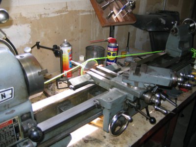
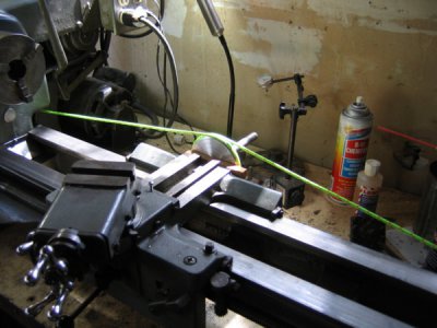
Getting closer on my taper attachment. The trial wheel is done. All that is left is drilling and taping the coupler nut to hold the shaft to the lead screw and threading the shaft for the nuts to hold the wheel in place. I also need to decide on what I am going to make the end plate on the cross slide out of. Using a temporary wood block for now. Took pictures of everything sitting in place so you could get a visual of how it all fits together. Used the bright lime green line so you could see it. I have other line that is smaller and stronger but might not have shown up good in the pictures Might get it done tomorrow evening.

IMG_3556.JPGIMG_3555.JPG
 
This afternoon I checked the rotation to see whether the line needs to feed over the top of the wheel as shown in the pictures or under the wheel to get the correct rotation. Turns out that the line needs to feed under the wheel. I threaded the outer diameter of the wheel to 8 tpi to keep the line from overriding itself. 10 tpi would have been better. I have also come to realize that having threads won't work for more than two revolutions because the line will feed off the wheel as the wheel turns. I won't thread any other wheels that I make. Instead I will have a lip that extends up to keep the line on the wheel.

I am also going to try casting a wheel out fiberglass like I have done to make sheaves for blocks on my sailboat. It was time consuming for me at least to machine the wheel out of aluminum bar stock. A molded wheel would be closer to final dimension and hopefully only need a small amount of machining to finish it.

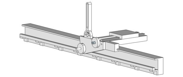
Forum member Uglydog and I have been exchanging emails about using gears to drive the cross slide lead screw. If the line and wheel doesn't work out I may try making a geared taper attachment. Here is a sketch of my current thoughts on how to use gears.

geared taper attachment ver 02.jpg

The rack is 10 tpi. The rack drives a 40 tooth gear that doesn't show in the sketch The 40 gear is on the same shaft as the lower left gear in the sketch and both gears turn together. The lower left gear through an idler drives the upper right gear which is connected to and turns the cross slide lead screw. I worked out some of the gearing needed for taper angles up to 4 degrees and tapers for MT0 to MT4. The biggest gear is a 180. That can probably be reduced in size by making the idler a compound gear. I haven't tried to work that out yet. The arm that is sticking up pivots so the idler can mesh with the other gears. The pivot arm could also point down instead of up if there is enough room to do this.
Anyway just another way to do this.
 
I had thought ,a bit, of using gears to drive the carriage but with several years of projects already on the list I didn't fully think it through.
What I considered was that they could provide a more uniform travel when cutting threads.
The accuracy of precision lead screws is expensive to produce by grinding and even the middle grades that will hold 0.001/ft are out of my income range.
This use of cable and wheels is perhaps a better idea. I cant see why it wouldnt be a better for both tapers and threading so long as it's positive in the high force needed to cut threads. That might just mean two or three wraps of the cable and a stronger cable to avoid stretch. The system could use step down gearing and larger wheel diameters to get the needed force.
The larger the line, wire, or cable diameter ,the larger the diameter of the wheels must be.
I haven't a clue how to calculate force to cut 4TPI or any other thread.
Still, the thought of a constant feed system that wouldn't mirror errors of the lead screw is interesting and a tool post grinder could be used for the final passes to produce a nice accurate screw as long as your carriage can travel.

Wire or cable are better choices for a drive line as its much easier/more accurate to use their diameters in calculations.
Even the best rope will flatten when wound around the sheave so figuring diameter is trial and error and it won't be constant.
The force for turning tapers isn't going to cause the rope to stretch but higher forces are involved for threading.
The biggest problem I see in using gears for tapers is the number of gears needed would be expensive.
I think the system your trying now is cheepest and best.
I would use wire or cable and the attach points of the line shoudn't produce a force up or down on the carriage.
 
Last edited:
This is just for cutting tapers. Not intended to cut threads. The big problem with using wire or line is that as the taper gets larger the size of the wheel decreases dramatically. To overcome this you have to add purchase to the line. Wire does no like to turn complete circles. There are now small diameter lines used in sailing that are stronger than steel and have less stretch. And I think that it would grip the wheel better with less tension. Some of the new high tech fishing lines may also work. Their diameters are so small that it may not need to be adjusted for.
The tapers that I intend to cut are not critical. They just need to be smooth and even. So my wheel diameters can be off a little and still be ok. Hope to turn a couple of test tapers next week.
 
you are over thinking this , this is what i use , ball bearing center in headstock , and off set center in tailstock, use a face plate and cut taper between centers

101_0750 (1).JPG
 
I totally agree with you that I am over thinking this. I could have bought a boring head to fit in the tail stock and a live center to fit the boring head. Or I could just offset the tail stock. I would have been good to go to turn any taper that I wanted to. And I may end up doing that. On the other hand I like intellectual challenges. Figuring this out has been fun for me at nominal cost. I am retired and have joined the swelling ranks of the independently poor. Cost is a factor I have also thought about making a fixture like in your picture. I may try that too.
As I like to say. My plans are always cast in sand at low tide and subject to change.
 
Back
Top