Taper Using Compound

SE18

Active User
Registered
Joined
Feb 26, 2012
Messages
758
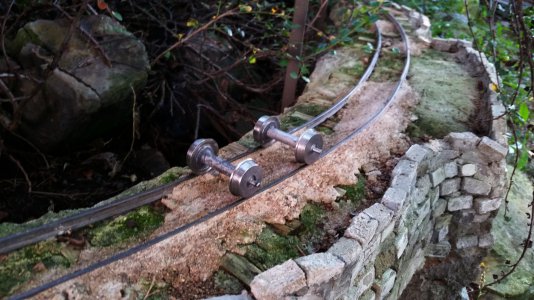
I've got a south bend 9A I'm using to do a 2deg taper on some wheels for rolling stock to tow behind this guy:


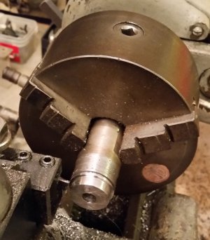
SB designed the compound markings on the rear side so you have to either go around the lathe to read them or use a mirror. Also, to do the taper, it seems the only way is to go past the zero mark, which I did, where there are no markings. I got 2 degrees past zero using a ruler; wish it were easier. This, btw is 1:13.7 scale representing 2 ft gauge.
20150919_105229.jpg 20150919_175232.jpg
 
On my Logan I simply scribed a reference mark on the front so that I could turn the compound past zero and still set it accurately.
 
One way to set a shallow taper is to set up a cylinder in the chuck for a reference point. Mount a tool in the tool holder and adjust the cross feed and carriage to just contact the reference cylinder. Note the cross feed setting. Run the compound slide 1" or 2" and readjust the cross feed and carriage to re-establish the contact with the reference point and note the new cross feed setting. The ratio of the cross feed travel to the compound travel will be equal to the sine of the compound angle. In the case of a 2 degree angle, the ratio will be .03489.

If your compound travel is 3 or 4", you can get fairly accurate angle settings this way. An indicator rather than observing tool contact will also improve accuracy. If it is a commonly used setting, once the angle is set, a scribe mark can be made for ease of resetting.

Bob
 
I've got a south bend 9A I'm using to do a 2deg taper on some wheels for rolling stock to tow behind this guy:


SB designed the compound markings on the rear side so you have to either go around the lathe to read them or use a mirror. Also, to do the taper, it seems the only way is to go past the zero mark, which I did, where there are no markings. I got 2 degrees past zero using a ruler; wish it were easier. This, btw is 1:13.7 scale representing 2 ft gauge.

I rotate the compound clockwise so that the hand wheel faces in the operators direction (a much easier to use position), run the spindle in the reverse direction and use a RH OD turning tool on the back side of the part, a LH boring bar works well for this if the taper is short. Also have used a RH straight turning tool on the back side held upside down with the spindle running in the forward direction. Do what works and is the quickest most comfortable setup on your particular machine. There is no Right or Wrong way to do any job so long at the method falls within the time constraints and machine capabilities, be creative and use whatever methods work for you.
 
thanks all, good suggestions! I'll try all of them in the future. I hesitate to run the spindle in reverse b/c it's a screwon, but this seems interesting too " Also have used a RH straight turning tool on the back side held upside down with the spindle running in the forward direction."
 
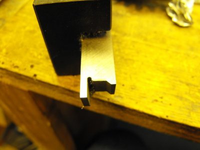
I model in 20.3 scale and this is the tool I use to make my wheel contours. It is ground close to the the contour that Gary at Sierra Valley uses on his wheel sets. It doesn't look like it has a taper, but it does and the wheels track very well.


pfPeH3.jpg

Rodney

pfPeH3.jpg
 
I have Little Machine Shop's set of angle gauges. On my Logan, to set the compound's angle, I run the apron over to the left, and pinch the angle gauge between the chuck and the side (or end) of the slide. (For a steep angle you'd use the side; for a shallow angle, use the end.) Some adjustable arm protractors could support this technique as well.
Greg
 
Last edited:
thanks all, good suggestions! I'll try all of them in the future. I hesitate to run the spindle in reverse b/c it's a screwon, but this seems interesting too " Also have used a RH straight turning tool on the back side held upside down with the spindle running in the forward direction."
Tool "upside down" on the side of the part away from the operator, same tool and same forward spindle rotation direction. One advantage is that if you run out of room for another tool on the front side then turn one over and run it from the back side. A disadvantage is that it may be difficult to see when setting the tool this way on an engine lathe, one advantage however is that the chips will often fall straight down into the pan, do whatever works for you.
 
Rodney, wow, I was thinking of grinding something for the flange but you got the entire profile. I've purchased wheels from Gary in the past (there are two Gary's in California (Gary Watkins is one) and I get them confused). Both sell your gauge and mine. I so far just do straight wheels but he does steel wheels in curly spoke, which the machining is a bit beyond my basic knowledge, although I did carve a blank once in wood and cast some in a solder/lead mix poured in an RTV mold.
 
Back
Top