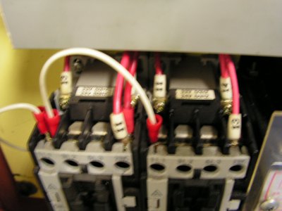
Teco 7300 CV

Hi Kenny
I don't have a rotary drum switch, I have a cutler hammer 3 position rotary switch ( this is a maintained contact type of switch). For this type of switch you buy the contacts separately and mount them in the switch housing, you can buy NC, NO, dual NC or NO or a NC/NO. You can mount 3 "micro switches" in the switch housing. I agree that using a braking resistor and the normal VFD stop logic(I hesitate to call it a switch) is the fastest way to stop the lathe.
My background and training though force me to view an Emergency stop switch as an ESD where you kill all energy to the unit hence I have to kill the power to the VFD( what if it is the one loosing its smoke)
anyway that's my story
Gord


I am confused.

Why do you think you need to add microswitches to your rotary/drum switch?

Why would you have your e-stop kill power to the VFD? You can program it to stop the machine a lot faster than it coasting if the power is removed-especially if you add a external braking resistor.

Read this thread for reference: http://www.hobby-machinist.com/show...e-off-forward-switch-to-vfd?p=26771#post26771
 
Pictures are helpful so I look forward to seeing them
thanks
Gord

I try to keep it simple. If you want I could take a few pics of my wiring and post more details this afternoon.
 
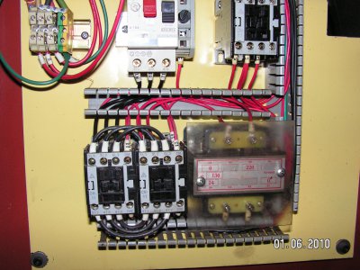
Here is the pics. The first pic is original wiring, 240v 3 phase input.

PICT0110.JPG
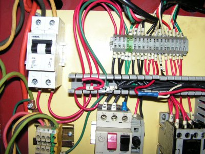
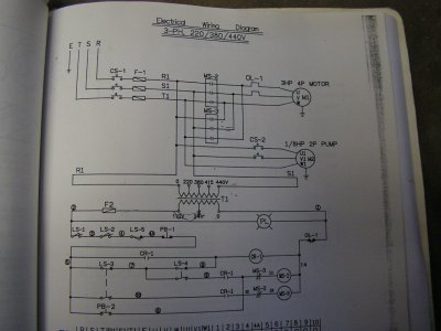
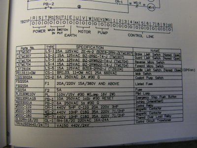
Second pic shows 240v (120v+120V) in thru 30 amp breaker up to top left of terminal strip to R,S terminals. T was disconnected. From there the power goes thru the main disconnect rotary switch on the front of the lathe then back as R1, S1 to the original overload in the lower centre of the pic. The S1 wire goes in the top and I have the bottom line out go into the top where T (which is also disconnected) would go. The T line out and the R line out go to the VFD power in. I jumped S out to T in for load sharing on the overload. I had to dial it up from 6 to 10 amps to stop it tripping under heavy load/cutting.

PICT0728.JPG

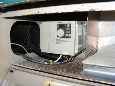
the thrid pic show the drive mounted in the tool box under the lathe. The two black covered cables are 240v in and out direct to the motor. The grey cables are shielded communication cable that run out to the motor direction contactors and up to the speed pot. The white cable is a Cat5 RJ45 network cable running up to the remote keypad/display unit.
PICT0732.JPG

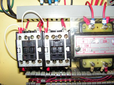
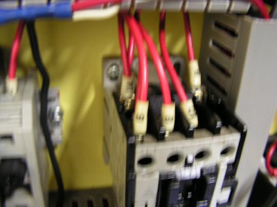
The fouth pic shows the VFD fwd/rev common white into the top of the contactors, with the black and red out the bottom for fwd or rev. Wired up this way the E-Stop switch acts as a stop command for the inverter which uses braking without a seperate resistor. Make sure you find the parameter for automatic restart and shut it off. That way if you tap the brake pedal or hit the E-Stop it doesn't restart when cleared. I have to return the apron lever to off before it will restart.
PICT0729.JPG

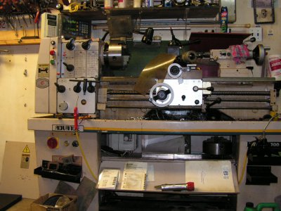
This last pic shows the remote keypad and tachometer display mounted up beside the DRO and the speed pot above the E-Stop switch.
PICT0733.JPG

PICT0110.JPG PICT0728.JPG PICT0732.JPG PICT0729.JPG PICT0733.JPG
 
I like the idea of using shielded communication cable for control wiring. Ah yes shut off the auto restart - Great comment. I will be studing your pictures closely looking for other tricks

thanks
Gord

Here is the pics.
The grey cables are shielded communication cable that run out to the motor direction contactors and up to the speed pot. The white cable is a Cat5 RJ45 network cable running up to the remote keypad/display unit.

The fouth pic shows the VFD fwd/rev common white into the top of the contactors, with the black and red out the bottom for fwd or rev. Wired up this way the E-Stop switch acts as a stop command for the inverter which uses braking without a seperate resistor. Make sure you find the parameter for automatic restart and shut it off. That way if you tap the brake pedal or hit the E-Stop it doesn't restart when cleared. I have to return the apron lever to off before it will restart.
 
Did you found out about the switches? I'm facing the same problem, just with a Bridgeport mill.
It seems from the diagram that those switches are momentary ones, but I would appreciate any input on this myself.
Stop+Run are momentary and the forward/reverse are not? It's confusing.
 
If you can hang on till next week, I will have it wired and I can report back what I did - what worked or didn't work or what I am stumped on. Been a extremely busy summer for me so finally back to the lathe.
Gord
 
I think that I have got it now, but it would be nice to be sure then sorry.
 
Finally I had some time and I installed it and it's working great.
I have two questions about the display on the drive itself, the display should blink constantly? It kind of irritates me.
The second issue I have is how do I match the RPM on the display with the spindle of the mill?
 
My display will be covered by the panel cover when I get the control wiring sorted. So my Teco display will not be visible during normal operation.
The Teco cannot display RPM, it displays frequency. To display rpm you need a tachometer. There are a couple of suppliers that I know about Little Machine Shop http://littlemachineshop.com/products/product_search.php?critFast=tachometer&B1=Product+Search
and a build it yourself model from mach tach http://www.machtach.com/
Gord

Finally I had some time and I installed it and it's working great.
I have two questions about the display on the drive itself, the display should blink constantly? It kind of irritates me.
The second issue I have is how do I match the RPM on the display with the spindle of the mill?
 
Back
Top