Testing A Motor Start Potential Switch

Shiseiji

Avid destroyer of many materials.
H-M Lifetime Diamond Member
Joined
Sep 14, 2014
Messages
438
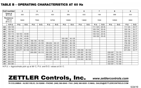
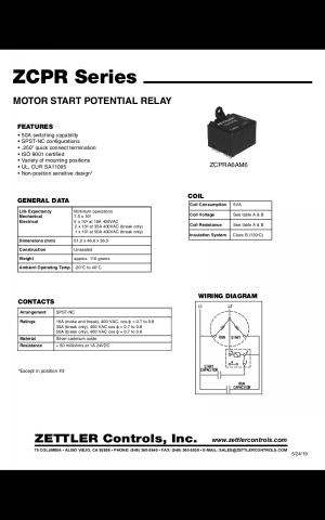
Hello, Happy Holidays and a not receiving a quick answer is not a crisis. I have a static phase converter with a Zettler ZCPR series , 5 coil I want to test and need guidance. I'm trying to figure out if I fried it pulling momentary 89a through it. Table A is for 60hz. In learning that "P.U." is pick up value and "D.O." is drop out value (professional peeve against any initials, initialism, or acronym not spelled out at least once in any document), haven't figured out what "H.P.U" is yet (hysteresis? the feed back voltage? ), but I figured out how to read the table.

Mine is an "AI" series.
The listed max break point is 50a
My input voltage is 243.
Resistance is 10k ± 10% @ 25°C/70°F.
V max is 395
PU is 203v
DO is 60 - 130v
H.P.U is ~ 220v - 240v @ 90°C/194°F

As a reference I have a 3hp 10EE I'm testing. The peak start amperage is ~ 89 and settles out @ 11.

How do I test it?

TIA

Ron
Screenshot_20221224-171241.png

Screenshot_20221224-171346.png
 
From the data sheet, H.P.U is “approximate hot pickup” @ 90C.
 
I have one of those in my RPC. It is basically a relay that is calibrated to open/close at certain voltages. It swings the contact from the pins 2-1 to pins 2-4 when sufficient voltage is reached. 2-5 is the electromagnetic coil that activates the relay. HPU is hot pickup voltage, i.e. at 90 degrees C, how much voltage closed the relay. DO is dropout voltage (how low the voltage must go to re-open the contacts once they are closed). There should be a digit after the AI that gives you which column in the table to read those values from.

For a basic test, you need an voltmeter and 240VAC source (i.e., a common 240VAC outlet).
First test it totally unpowered, you should get pins 2-1 connected (very low resistance), and some resistance in the range of 5k to 14k (depending on which column/part number) from pin 2-5. Pin 4 shouldn't connect to anything (infinite/very high resistance).

Then connect 240VAC across pins 2-5. Yes, that is potentially lethal voltage! Measure the voltage across 4-5. You should get 240 volts.

If you get these results, you can pretty safely assume it still works. This doesn't test the actual voltage values that it kicks in/out, but does give you basic go/no-go answers.
 
Last edited:
Potential relays are sensitive devices, in the sense that they fail easily.
The purpose is to dump the start capacitors charge into the starting circuit to either start the motor or bring it back up close to rated speed during high load events .
The more times the potential relay is called to work, the more heat is produced in both the start capacitor and the potential relay.
This is perfectly fine for a couple cycles per hour, but if the potential relay is called to act many times in a minute, the capacitor and the relay are sure to fail in short order.
To mitigate this problem, a momentary normally open switch can be placed on the generated leg, isolating the potential relay from the start circuit. The momentary switch is used for starting only.
The start circuit and potential relay will now have extended life
 
I have one of those in my RPC. It is basically a relay that is calibrated to open/close at certain voltages. It swings the contact from the pins 2-1 to pins 2-4 when sufficient voltage is reached. 2-5 is the electromagnetic coil that activates the relay. HPU is hot pickup voltage, i.e. at 90 degrees C, how much voltage closed the relay. DO is dropout voltage (how low the voltage must go to re-open the contacts once they are closed). There should be a digit after the AI that gives you which column in the table to read those values from.

For a basic test, you need an voltmeter and 240VAC source (i.e., a common 240VAC outlet).
First test it totally unpowered, you should get pins 2-1 connected (very low resistance), and some resistance in the range of 5k to 14k (depending on which column/part number) from pin 2-5. Pin 4 shouldn't connect to anything (infinite/very high resistance).

Then connect 240VAC across pins 2-5. Yes, that is potentially lethal voltage! Measure the voltage across 4-5. You should get 240 volts.

If you get these results, you can pretty safely assume it still works. This doesn't test the actual voltage values that it kicks in/out, but does give you basic go/no-go answers.
Ah, "hot,", thanks.
I probably tried too hard to not post too much, yes the full part number is:
ZCPRZ5AI1 and I should have just posted page 3 as well. Sorry.

I will wire it up with a plug and 1/4" spades for the test and have a nice new Kline meter, with a capatance test!, and insulated clips so won't be Mickey Mouse gambling with the voltage! Constant memory of some poor Apprentice, poorly supervised, in a factory killing themselves.

Long ago for a short time I had a job doing final reassembly of the after burner fuel control for F-14 powerplants. One of the final tests was a hysteresis of one of the valves. So I was curious if was possible to cobble together something with out major investment for basically what I hope is a one off test. Will do the make break test and call that good enough. Appreciate the assistance.
P.S. in a family of professional machinists and engineers, I'm the odd one out who struggled with every math class and was happy with a "C.". But statistics made a deep impression on me and really changed how I view things. Big smile when I read your tag line. I first read of it in a Robert A. Heinlein story, IIRC about when someone would be released from purgatory

Ron
 
The more times the potential relay is called to work, the more heat is produced in both the start capacitor and the potential relay.
This is perfectly fine for a couple cycles per hour, but if the potential relay is called to act many times in a minute, the capacitor and the relay are sure to fail in short order.
Hence the manufacturers warning about start cycles. I've read how easy it is to surpass the capabilities of a start cap. Neither of m caps appeared/smelled damaged but I was still pleased when the capatiance test confirmed the simple VOM test I'd done. My work on this was interrupted with a move from VA to WA and all the associated headaches.

Ron
 
It’s a footnote on the data sheet, pretty easy to miss.
Thanks, I saw the footnote on how to arrive at the value, but I think the manufacturer assumed anyone looking at the sheet would know what "D.O.", P.U.", and " H.P.U." mean. Not true in my case, but no trouble understanding them once enlightened. Too focused on finding an exact match.

Ron
 
Really, I have never seen those abbreviations used before. I agree with you completely about using initials or acronyms without explanation. It’s lazy or worse.
 
Back
Top