The never-ending saga of the Hurco that's "ready to make parts"

Re: Code issue, please help. This stopped being fun a few days ago.

OK, max rapid is 250 so I set it at 25 and checked the voltage. Got it pretty much equal in both directions at .510 volts ±.002. Ran my favorite test circle and still have the 6 and 12 o'clock offset although it is decreasing in severity.


I did notice a slight thud when the Y axis changed directions that the X does not have. I didn't get a chance to write the code for the 2" movement yet to check the accuracy of the movement but now I'm wondering if I also have a backlash problem. I didn't see any thrust bearings on the body of the mill but I'm also not sure exactly what I'm looking at. My small CNC has thrust bearing on the handwheel side of the ballscrew that can be tightened. Are the large CNC's made the same way? That pulley appears to on there pretty good and I don't want to break it just for some exploration.

Anyone have experience with this?
 
Re: Code issue, please help. This stopped being fun a few days ago.

With the power off, put a dial indicator on the table and rotate the motor/ballscrew by hand and check the backlash. If the ballscrew turns a bit before the dial indicator moves, then it time to start looking at the mechanical parts. You can check the end play in the ballscrew by putting an indicator on the end of the ballscrew and rotate back and forth. There should be zero end play.

The end play should be set by the nut holding the pulley, but your mill may use another method of adjusting the end play.

If the end play is OK, then the problem is in the ballnut and it will have to be adjusted.

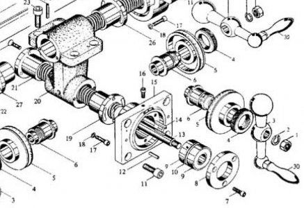
I think your machine is put together like this: (The handwheel is replaced by the pulley, but should be pretty much the same design)

Y-Axis.JPG
 
Last edited:
Re: Code issue, please help. This stopped being fun a few days ago.

Through a rudimentary arrangement of a square, protractor and a sticky note I've discovered that there is some endplay and it is resulting in approximately 5º of rotation of the pulley before the indicator moves. While 5º does not sound like a lot, I'm sure it can make a difference.

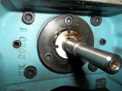
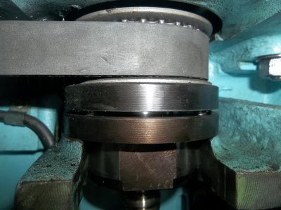
I got the pulley off and took a picture of what was under it.

100_0891.JPG

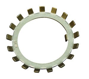
if you zoom in on the nut you can actually see that it has something below it that appears to be a lock washer like the picture below. I did not take anyhting apart as I would like to get input first.

0437800.jpg


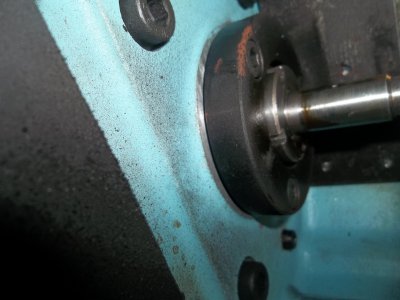
If you look from the side you can see a space between the mill body and the black item that looks like it can be tightened.


100_0892.JPG

Here's a better shot of the Z axis that shows this better.

100_0893.JPG


Any guesses as to where the adjustment for tightening should be? I'm guessing the nut with the spanner wrench holes but I don't want to screw anything up.


Thanks,
Corey

100_0891.JPG 100_0892.JPG 100_0893.JPG 0437800.jpg
 
Re: Code issue, please help. This stopped being fun a few days ago.

I would say that 5* rotation is huge in a CNC, that's probably about 0.003 or so, couple that with some backlash in the ballscrew and it may be quite a bit more.

The black ring locks the OD of the bearings into place, in other words, it captures the bearings in the bore of the housing. This should be pretty snug. The nut with the lock washer is what sets the pre-load on the bearings. This should be adjusted to just over finger tight, plus an additional amount to align the next tab with the notch in the nut. The ball screw still should turn freely, but should have a light resistance due to the bearing pre-load. There are probably torque specs on all of this, but I just use my experience and feel.

Once you adjusted the pre-load, then check for backlash in the ballscrew. Put an indicator on the table, and rotate the ballscrew. If it is correct, any movement in the ballscrew will cause the table to move. If this is not the case, then you will have to adjust the pre-load on the ballscrew nut.

You may be able to reach up under the knee to do this, if not, it may require that you remove the bearing housing, the part labeled HK 2020 1, and go in from there. Look at the drawing in my last post. The ballnut should have a slotted mount, that when you rotate a bit will pre-load the ballnut.
 
Re: Code issue, please help. This stopped being fun a few days ago.

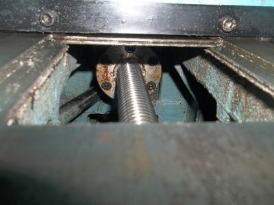
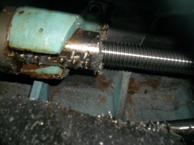
I adjusted the end nut which barely moved and no noticeable difference so I watched the screw as I rocked the pulley back and forth and looks like all the play is in the ball screw. Unfortunately, my ballscrew does not have the slots as shown in the picture referenced above but rather looks like so...


100_0896.JPG100_0894.JPG


I guess I'll be pulling it out to check the condition and to see if there's any way to adjust it but my initial google research says there isn't. I don't really want to rebuild a ballscrew but it's leaning that way.

Any thoughts?

100_0896.JPG 100_0894.JPG
 
Re: Code issue, please help. This stopped being fun a few days ago.

I wish I had a easy answer for you, but I'm afraid that I agree with google in this case. I don't see any way to adjust that ballnut. Normally an adjustable ballnut system consists of two nuts that are tightened against each other to pre-load the system, in this case, it looks like a single nut.

Do a google search for rebuild ball screws There are a number of companies that do this. I don't think this can be done in the home shop. I have no idea what the cost might be. I would balance the cost of having a rebuild done vs. buying ballscrew off of fleabay and modify it to fit.

I had a similar problem with my mill, but I solved it by putting 1 micron magnetic scales on the table rather than rely on the encoders for positioning. I am looking at the actual table position, doing it this way takes all of the ballscrew variables out of the equation.
 
Re: Code issue, please help. This stopped being fun a few days ago.

The amount of slop equates to just about .004" and the ball screw appears to be the only culprit left. It appears as though I have some decisions to make.


There are a few ball screw rebuilders that are recommended on a few forums and I'll get some pricing from them before I do anything stupid. From my research it appears that the balls are the first to go (wear), the nut next and the screw last. Seems to make sense. If that rebuild is too expensive I might try to rebuild it myself. What have I got to loose if I'm gonna end up replacing it anyway? I know the slop dimension and once it's apart I'll know the dimension of the balls in the nut. I can do some math and figure out what the ball dimension should be and give it a shot. This is contingent of course on a visual inspection of the screw showing no signs of damage. The video below gives a brief overview of the process and I read where a few guys have done it successfully but it was not easy. Almost nothing in my garage is easy so nothing new there.

https://www.youtube.com/watch?v=dGp56l0bsdA


My preference will be to let someone else do it but I need to have a backup plan.

One more thing I'll do is check to make sure all the attachment bolts are tight before I take it apart. A loose bolt here or there could result in a bunk reading. It's a little hard to get to but I'll need to take it apart to get it out so I might as well check the tightness before I take a bolt out.
 
Re: Code issue, please help. This stopped being fun a few days ago.

I have reloaded a few ball nuts, a rather tedious job but not difficult. One time I had to do it on a vertical ballscrew, with two opposed nuts, in place on the machine. That was a bit more challenging.

I suspect that there will be a bit more tuning needed on your servo also, but that will be for another day.

Best of luck. Please let us know how it works out.
 
Re: Code issue, please help. This stopped being fun a few days ago.

I figured I wasn't done with the servo but I think I need to eliminate the slop to get accurate readings for everything else. You're right, another day for that.
 
Re: Code issue, please help. This stopped being fun a few days ago.

Opps.. Sorry gang. I did not travel to the end of the chain here... disregard.... But man... This is a wicked one for sure!
Jeff.

The pots (adjustable potentiometers or variable resistors) are indeed the blue squars w/ orng loctite type material. there are also several on the top of the picture. If I recall the old day's those we called "10" turn pots since they offered better resolution to a fixed signal point. I see BAL SIG AUX TAC etc... on them.
 
Back
Top