- Joined
- Apr 23, 2018
- Messages
- 6,567
Two threads came up in the last month about creating noncircular arcs with conventional mills (in my case a 2" face mill). One option presented was to tilt the mill head to create an elliptical curve along the X axis. While this creates a climbing cut that can't be corrected (spiral motion into an interrupted path), it seemed like one way to get it done.
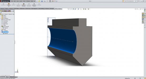
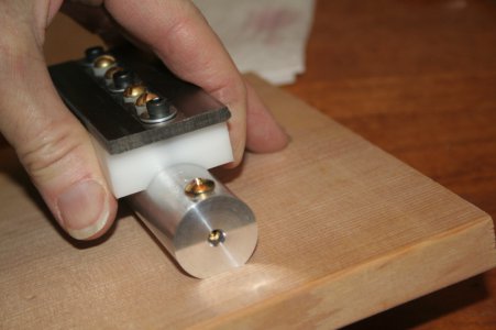
I've been working on a design for a shop-built press brake, and decided to make my own dies (of course). I thought I'd try this technique in Solidworks and see how it works out. I knew that it would form a true ellipse with the minor radius equal to the cutter radius and the major radius equal to the sum of the cutter radius and the sine of the head angle.
Turns out that even with a reduced depth of cut (machine z offset) the angle has a limit. I tried 15 and 20 degrees, but to get the depth I want for this case I would have to run this cut a lot closer to horizontal. That gets way outside the tool's intended work envelope. So my take home message is that this technique is okay for shallow cuts, but gets ugly quick as you try to go deeper.
Decided it's better to try to make my brake die clearances another way, but I thought I would share my result since it has a picture to go with it, and the technique may be useful at some point.


