

-
Welcome back Guest! Did you know you can mentor other members here at H-M? If not, please check out our Relaunch of Hobby Machinist Mentoring Program!
You are using an out of date browser. It may not display this or other websites correctly.
You should upgrade or use an alternative browser.
You should upgrade or use an alternative browser.
[How-To] Threading a chuck backplate
- Thread starter Jim F
- Start date
- Joined
- Jan 31, 2016
- Messages
- 11,446
Yep , a 2 internal will fit a 3 external . Hope to be up tonight , fighting an infection on a toof and taking Advil , Amoxilcilin and Coors light to fight it off . They wore my arse out at work last night . Don't mind the working part , but when the new employees come from the City District Re-enterisation plan , it gets old . My plans are changing . 
- Joined
- Mar 21, 2018
- Messages
- 1,597
There seems to be some misunderstanding about the functions of the various surfaces of a threaded spindle: the thread simply tightens the chuck against the annular surface (aka vertical flat). The annular surface provides precise axial positioning but neither the annular surface nor the thread provide accurate concentricity - this come from the precisely machined cylindrical surface on the spindle.
Yes, there is some misunderstanding - this comment is NOT true. The surface between the threads and the spindle shoulder does NOTHING to register the chuck. Most chucks made for South Bend lathes have clearances here of 0.005 to 0.010". This area is just "the space between the end of the thread and the spindle shoulder".
Lest anyone get angry at this, let me explain:
Take an imaginary and simplified spindle and backplate:

In this scenario, the counterbore has a 0.010" clearance.
Assemble the two:

As they are assembled, the force the spindle is pushing back must be balanced by the force the backplate is pushing forward. During assembly, gravity is making the force per unit area higher on the top of the assembly than on the bottom. Once contact is made with the spindle shoulder, the forces on the top of the thread will continue to move (up, in this instance, as it is the only way it can go) until it is equaled by the forces on the bottom, which are trying to move down (the only way THEY can go). Once equilibrium is reached, both the bottom force and the top force will be the same, as they have fought each other to a standstill (literally). Where do they meet? In the proverbial middle. And where is the "register"? It is now 0.005" off the spindle - exactly where you would expect it.

Now, what would happen if the register would be making contact (at the top, since gravity would insist on this)? That means that the backplate (and thus the chuck) would have 0.010" of clearance on the bottom. If it was machined like this, the machining would remove this error - for this orientation. With the plate machined with this error, once the chuck was removed, you have lost this registration. The only way this registration could be repeated, was if the spindle was in the EXACT SAME position on the lathe (call this point 0º). If the spindle was rotated 90º, the error would start showing itself, because in this scenario, it is the "register" that is registering things and not the shoulder and threads and gravity would enforce its laws. The error would continue to get worse until the spindle was at 180º, in which case the error would be double (or 0.002").
In my simplified scenario, I break the forces into a top and bottom force. In reality, the forces are equally distributed over the entire face of the threads, but the simplification still holds true.
The better the fit that the backplate has to this plain part of the spindle the closer the chuck will be to the axis every time you screw the chuck off and on again. You won’t get a turned thread in cast iron accurate enough for the sort of repeat concentricity that a chuck needs.
You don't need a precision thread here - all the thread has to do is be the same pitch as the spindle and it will push the back plate tightly against the vertical register. And this is repeatable, installation after installation. Sub thousandths runout with clearances in the cylindrical area of 0.010" is not uncommon.
Now if you still think that the cylindrical area is a register, just think of what it would take to make it a register. Make yourself a cylinder 1.500" in diameter and a hole also 1.500" in diameter, then try to fit them together. You'll find that it is no easy task. To produce chucks with near a ±0.0005" tolerance hole would greatly increase the cost.
Registers on chucks like the D series and L00 type have tapers for the registers. A non self-holding taper repeatably registers itself with very little runout.
")
- Joined
- Jan 2, 2018
- Messages
- 42
SLK001 - I follow your argument and see how it can work for a vee thread, but when I apply the same thought process to a square thread it doesn’t work and that worries me. It makes me feel that it just happens to work rather than it intended to work this way.
To pursue this interesting discussion a bit further (and thanks for keeping it civilised by the way) I looked around at international standards for threaded spindle noses. Here’s an example: DIN 800
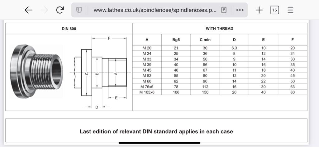
As we’ve agreed, the threads (A) don’t need to be precise but the spindle’s plain diameter (B) is quite closely toleranced (g5). Why do this if it’s not needed? I haven’t found corresponding standards for backplates though, so for me the discussion is still open. I’ll get back if I find more evidence!
Sent from my iPhone using Tapatalk
To pursue this interesting discussion a bit further (and thanks for keeping it civilised by the way) I looked around at international standards for threaded spindle noses. Here’s an example: DIN 800
As we’ve agreed, the threads (A) don’t need to be precise but the spindle’s plain diameter (B) is quite closely toleranced (g5). Why do this if it’s not needed? I haven’t found corresponding standards for backplates though, so for me the discussion is still open. I’ll get back if I find more evidence!
Sent from my iPhone using Tapatalk
- Joined
- Mar 21, 2018
- Messages
- 1,597
SLK001 - I follow your argument and see how it can work for a vee thread, but when I apply the same thought process to a square thread it doesn’t work and that worries me.
But I think that it does. In my example above, I concentrated on the forces forcing the chuck up the threads. There is also a force radially across the face of the thread. In a square thread, the radial force is the dominant force (if not the only force). Since the radial force isn't in line with the spindle axis, you have to break it down into it's "X" and "Y" axis components.

Some of the "Y" components are forcing the chuck up (look at the thread from the front side) and some are forcing the chuck down (the back side). The chuck is simply tightened until all the forces are equal. Since every individual point will have its Fy in a different direction (see below), the chuck will be properly tightened when the sum of all the forces is zero.

Then there is the question as to why the "B" dimension requires the tolerance that it has. Perhaps it is so other manufacturers can assure that their counterbore is sufficient to give adequate clearances. I've heard that some manufacturers like to counterbore their chucks very close to the spec (I don't know why, as this area still doesn't touch, or register when tightened). Maybe a close counterbore will put a limit on the amount of runout that can occur and the closer you are to the standard, the less that number can be. However, as that spec is approached, the more difficult it becomes to attach the chuck. As a hobbiest, the only threaded spindle lathes I have ever used are South Bends. All other lathes that I have used had more modern spindles like the D series. And South Bend has clearances in the non-threaded area of 0.010 to 0.020" and they still have excellent runout specs. I guess that you can color me "perplexed"!
- Joined
- Mar 3, 2020
- Messages
- 506
i Have a SB9 new in April ‘38. Workshop or toolmaker type.
My spindle register surface diameter is 1.494, the OD of threads is 1.492.
I purchased it 37 yrs ago with a Craftsman marked (Atlas?) very beat-up & abused 4 jaw chuck, probably installed when lathe was pretty new.
The backplate register bore measures 1.503 I know that a 4 jaw doesn’t need perfection here, as the jaws need to be zero’d anyway.
Couple years later I bought (from Rutland or Enco, can’t remember) a 5” three jaw chuck & a blank backplate threaded 1-1/2-8. The register bore on this backplate measures 1.511 which worried me when I fit it to the chuck, that is .017 difference.
When I finished fitting the chuck & backplate the chuck had 0.001 runout. Acceptable for me.
After 35 or so years and MUCH use I measured it again, same 0.001 runout, put in a 1” piece of ground & polished shaft, same 0.001 runout.
I recently purchased a new 5” 4 jaw chuck, then bought a Shars backplate to fit it to.
The register hole in the chuck is 1.514. This cannot be changed.
When zero’d in this Chuck has no measureable (by me, anyway) runout along the length of the ground and polish 1”
I have looked and nowhere can I find a register diameter in the specs on a backplate. All other measurements, but not the register diameter.
Maybe I’m not looking hard enough, dunno.
So this leads me to believe that as long as the flat mating surfaces on the spindle & backplate & chuck are the same, even if the register diameters are off a bit the chuck will run true. Guided by the threads?
In theory, the spindle-to backplate diameters should be an accurate fit.
In theory, theory and practice should be the same.
Sometimes this is not true?
- Joined
- Mar 21, 2018
- Messages
- 1,597
Exactly. The procedure for truing a backplate that is already threaded is to first, face off the back. This gives the vertical part of the spindle and your backplate a set of reference planes to mate. The second operation is to flip the plate, then true up the front and cut any needed steps (or pins), insuring that the back and front planes are parallel. Cutting the pin to closely fit the socket in your chuck is one of the biggest factors in your chuck runout measurements - the closer to line-to-line, the better the runout (and the harder to mate).So this leads me to believe that as long as the flat mating surfaces on the spindle & backplate & chuck are the same, even if the register diameters are off a bit the chuck will run true. Guided by the threads?