I will be in the shop today trying to get a few details done. I will have to slow down until I can order the pieces of brass I need. I could make these few parts from aluminum, but brass will look a whole lot better and I hate to cheat on quality at this point. I am going to get the elevation part done before returning to finish the tool holder.
-
Welcome back Guest! Did you know you can mentor other members here at H-M? If not, please check out our Relaunch of Hobby Machinist Mentoring Program!
You are using an out of date browser. It may not display this or other websites correctly.
You should upgrade or use an alternative browser.
You should upgrade or use an alternative browser.
Tool and cutter grinder build
- Thread starter Mark_f
- Start date
I noticed you left the tilt adjusting screws out? View attachment 96436 Was this on purpose or are they not called for. I use them to get that dead on adjustment of the wheel height.
They won't be needed. I am using a acme lead screw and bronze nut for elevation. At .050"per turn, I will have a micrometer dial on the elevator screw so I can set to .001" increment easily.
I also don't have the same fore and aft adjustment that you have to move the wheel in and out. My design is similar to the Bonelle, so I couldn't do the tilt feature. My arms slide in or out. That was why I chose the lead screw and nut for elevation.
I also didn't realize until I got going , the Bonelle has a fixed setting on the in or out wheel position. After seeing your design, Bill, I felt it was a good idea to make changes to have that feature and an accurate way to set the height .
I have the wheel head pretty well finished. Here are a series of photos showing the wheel head progress.
This is the lead screw cut to length and the ends machined. The ends turned out to be .339" when the threads cleaned up. This is an odd size (same as an "R" drill). this is not a problem as I will be making all parts anyway, so I can use any size.
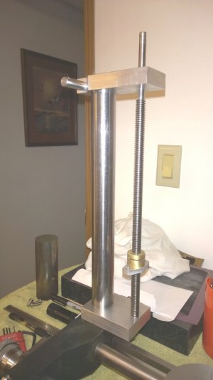
I made two support blocks for the screw. These had to be carefully machined because any inaccuracy here can cause the screw to bind.
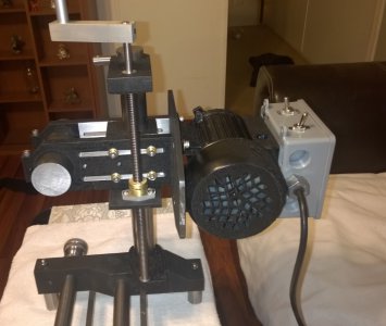
Jump ahead a few hours and the assembly is painted , finished machining, ant the motor mounted with the spindle blank inserted for the weight to check operation of the screw.
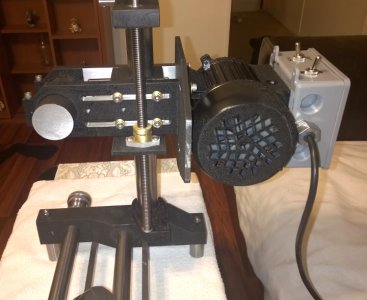
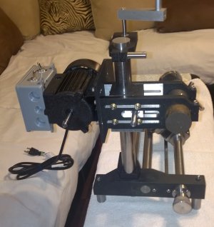
That ugly crank on top is TEMPORARY. It will be replaced with a hand wheel once I decide on a style. The screw works very smooth and seems to raise and lower the head assembly easily in each direction. There is also no detectable back lash. There will be a micrometer dial on top to position the head in .001" increments. The 1/2-10 lead screw gives .050" per revolution. I am extremely happy with the results of the wheel head. it was based on the Bonelle, which lacked some features I desired so I kinda reinvented it a little and changing to the acme lead screw was a good choice too. .... Oh,.... and yes I will be cutting the mounting tabs off the electrical box on the motor.
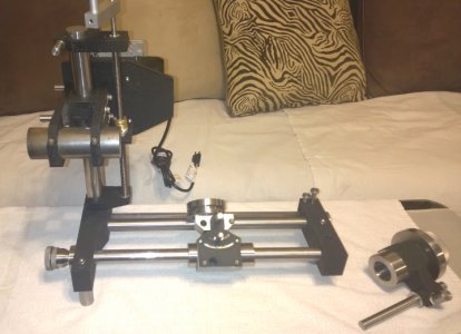
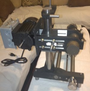
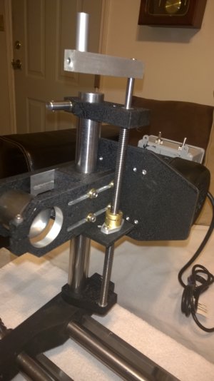


This is the lead screw cut to length and the ends machined. The ends turned out to be .339" when the threads cleaned up. This is an odd size (same as an "R" drill). this is not a problem as I will be making all parts anyway, so I can use any size.

I made two support blocks for the screw. These had to be carefully machined because any inaccuracy here can cause the screw to bind.

Jump ahead a few hours and the assembly is painted , finished machining, ant the motor mounted with the spindle blank inserted for the weight to check operation of the screw.


That ugly crank on top is TEMPORARY. It will be replaced with a hand wheel once I decide on a style. The screw works very smooth and seems to raise and lower the head assembly easily in each direction. There is also no detectable back lash. There will be a micrometer dial on top to position the head in .001" increments. The 1/2-10 lead screw gives .050" per revolution. I am extremely happy with the results of the wheel head. it was based on the Bonelle, which lacked some features I desired so I kinda reinvented it a little and changing to the acme lead screw was a good choice too. .... Oh,.... and yes I will be cutting the mounting tabs off the electrical box on the motor.


The shop was fairly warm today so I spent the day doing some details. They seem to take as much time as the major parts.
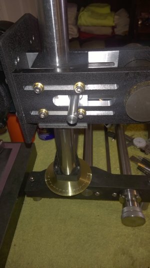
I made the bras dial that indicates the degrees when the column is rotated. It was a tedious process and my tired old eyes don't see as good as they used to. I tried to keep everything as perfect as possible. The 5 and 10 degree marks came out excellent. The one degree marks have a few errors but nothing major.
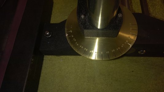
This is a closer view. the numbers were hard to do . I had to hand stamp them and keeping them even was difficult. there are a few out of place some but they are usable.
After the dial I spent the rest of the day making split cotters. I made them from aluminum because it is what I had. If they give me any trouble later, I will swap them out for brass.
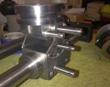
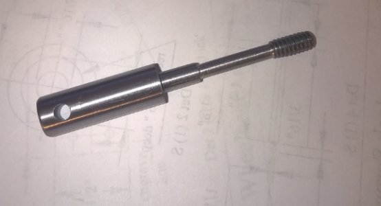
I made all the split cotters and handle bolts for the sliding base. The bottom one had a little too much interference into the bore. I wanted 1/4-20 bolts, but only had room a a 10-24. I had already made a 1/4-20 so I had to convert it to a chicgo bolt to make it work.
This is the bolt after being modified. It now works great.
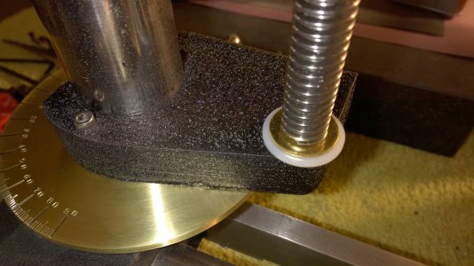
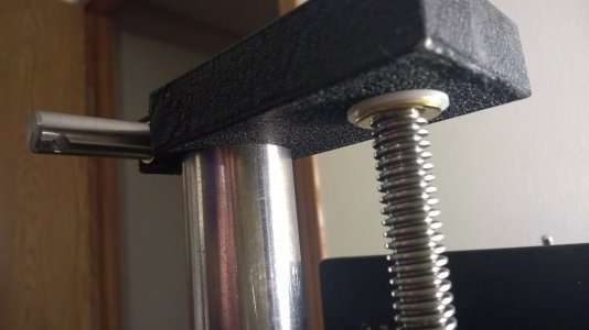
I also picked up some nylon bearing washers for the lead screw and will put them in tonight.

I made the bras dial that indicates the degrees when the column is rotated. It was a tedious process and my tired old eyes don't see as good as they used to. I tried to keep everything as perfect as possible. The 5 and 10 degree marks came out excellent. The one degree marks have a few errors but nothing major.

This is a closer view. the numbers were hard to do . I had to hand stamp them and keeping them even was difficult. there are a few out of place some but they are usable.
After the dial I spent the rest of the day making split cotters. I made them from aluminum because it is what I had. If they give me any trouble later, I will swap them out for brass.

I made all the split cotters and handle bolts for the sliding base. The bottom one had a little too much interference into the bore. I wanted 1/4-20 bolts, but only had room a a 10-24. I had already made a 1/4-20 so I had to convert it to a chicgo bolt to make it work.
This is the bolt after being modified. It now works great.

I also picked up some nylon bearing washers for the lead screw and will put them in tonight.
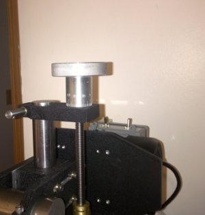
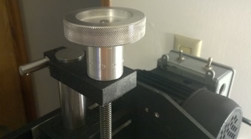
Spent the day making a hand wheel for the elevation screw on the grinder. Just to let you know, us old guys screw up too. I been saying for a week about the travel being .50" per turn of the screw. ( and none of you noticed my error). I spent hours machining a hand wheel , engraving lines and stamping numbers. the wheel came out perfect. I brought it in the house and put it on the grinder and it hit me. THIS IS A 1/2-10 SCREW! there are .100" per turn. I took the wheel back out to the lathe and machined the lines and numbers of to re do it. I now have perfect lines for .100" per turn, but I messed up the numbers bad. I will let them go untill I get the ambition to do it again ( if i ever do) . It will function fine, just the numbers are crappy.


Boy , I sure wish you had called me on that. Would have saved hours of work ...... LOLI was wondering where you managed to find a 20 tpi ACME screw, but thought I'd ask you about it later. Sorry...


