
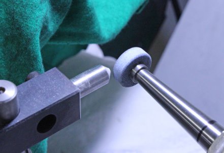
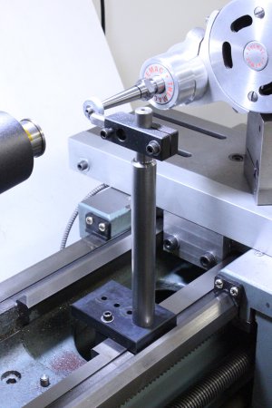
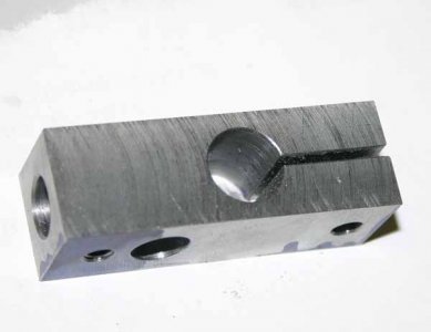
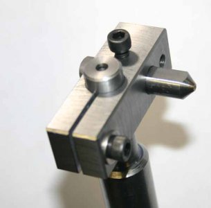
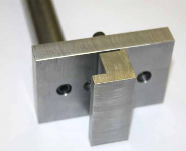
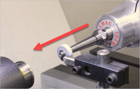
I made this up from steel bits & pieces. My idea was to have something which was preset to spindle center so it can be temporarily clamped on to lathe bed, dress the wheel then removed & get back to grinding. The diamond tool is the kind bonded into the tip of a 0.375" diameter shank available at most tooling suppliers. (Yes the lathe bed is all covered up when dressing & grinding, just removed for pics).

-
Welcome back Guest! Did you know you can mentor other members here at H-M? If not, please check out our Relaunch of Hobby Machinist Mentoring Program!
You are using an out of date browser. It may not display this or other websites correctly.
You should upgrade or use an alternative browser.
You should upgrade or use an alternative browser.
Tool post grinding wheel dressing apparatus
- Thread starter petertha
- Start date
- Joined
- Jul 2, 2014
- Messages
- 7,594
Typically, the dressing tool is mounted to the tool post grinder assembly so the wheel can be dressed parallel with the spindle, making a dead accurate dress without any measuring and without the setup changing as you move the compound and other axes to new positions. Tapered grinding wheels are not often needed or desired for tool post grinding, never in my experience.
- Joined
- Jun 7, 2013
- Messages
- 10,086
Never seen such a dressing device, Bob, pictures?
- Joined
- Jul 2, 2014
- Messages
- 7,594
No, John. Just thinking out loud, and maybe not thinking hard enough before hitting the "post" button...Never seen such a dressing device, Bob, pictures?

- Joined
- Jun 7, 2013
- Messages
- 10,086
Shouldn't you be out in your new shop-to-be arranging stuff instead of sitting in front of the computer ---- shouldn't I be doing the same? Too darn cold in mine!
Not quite sure I follow you Bob. With the dressing tool fixed to lathe bed, the carriage is traversed. TPG is mounted to compound, but compound is always locked, so TPG goes along for the ride so wheel gets dressed parallel to spindle axis. I move the cross bed travel inward to dress using DRO as guide (and then re-zeroed).
Maybe what you are getting at is I don't have control over the amount of grinding wheel removal relative to last position? The only way I'v eseen that done is something mounted on or in the chuck (which is not great if you have work in the chuck). If you have some pictorials that would be great.
Maybe what you are getting at is I don't have control over the amount of grinding wheel removal relative to last position? The only way I'v eseen that done is something mounted on or in the chuck (which is not great if you have work in the chuck). If you have some pictorials that would be great.
Attachments
- Joined
- Jul 2, 2014
- Messages
- 7,594
No, Peter, I was not thinking correctly. It has been some time since I used my TPG, and I simply did not remember what to do correctly. I plead a senior moment, and will leave this thread alone before I post something dumber yet... -BobNot quite sure I follow you Bob. With the dressing tool fixed to lathe bed, the carriage is traversed. TPG is mounted to compound, but compound is always locked, so TPG goes along for the ride so wheel gets dressed parallel to spindle axis. I move the cross bed travel inward to dress using DRO as guide (and then re-zeroed).
Maybe what you are getting at is I don't have control over the amount of grinding wheel removal relative to last position? The only way I'v eseen that done is something mounted on or in the chuck (which is not great if you have work in the chuck). If you have some pictorials that would be great.
HaHa no worries Bob. I was looking forward to learning something new. I haven't used my TPG much & there aren't really a lot of Youtube or instructional references to using them like conventional turning, milling or surface grinding operations.
I've been doing some internal grinding. The results are pretty good, not spectacular but slowly getting better with a few tweaks here & there. My hunch is that there are a lot of variables with TP grinding - stock material, wheel type, tooling, feed & speed, grinder stability, lathe background vibration... I wish I could see some more examples as a point of reference.
Next step is some home made arbors that I hope to make stiffer that ones I have. Themac has a funky taper unique to themselves for the tooling shank that goes into the mating spindle socket. I tried making a few test blanks by DTI-ing off the ones I have just using the compound. The fit is getting better but still not there. I may have to use the TS offset method (using a boring head). Once I have the dimensional taper recipe I'll be able to make some cool tools.
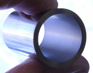
Pic of cast iron cylinder liner 0.0005" lapped #800 off after ID grinding.
I've been doing some internal grinding. The results are pretty good, not spectacular but slowly getting better with a few tweaks here & there. My hunch is that there are a lot of variables with TP grinding - stock material, wheel type, tooling, feed & speed, grinder stability, lathe background vibration... I wish I could see some more examples as a point of reference.
Next step is some home made arbors that I hope to make stiffer that ones I have. Themac has a funky taper unique to themselves for the tooling shank that goes into the mating spindle socket. I tried making a few test blanks by DTI-ing off the ones I have just using the compound. The fit is getting better but still not there. I may have to use the TS offset method (using a boring head). Once I have the dimensional taper recipe I'll be able to make some cool tools.
Pic of cast iron cylinder liner 0.0005" lapped #800 off after ID grinding.
Attachments
The other thing I should have mentioned is that the base of the dressing tool buts up against the lathe bed rail. So theoretically that is a repeatable position of the dressing point & therefore the grinding wheel relative to spindle center plane. Even though the wheel is getting smaller by dressing, the contact tangent should be a somewhat repeatable if I reset my DRO.
In reality I found ID grinding to be a bit weird. Its kind of like boring where you have to take the equivalent of a spring pass. But after measuring the bore progression vs carriage in-feed, there is still a bit of dimensional drift. My feed measurement is pretty good, I have a tenths indicator hard mounted to the table. But maybe the wheel OD is eroding a bit as I'm grinding, so its not like a single point cutter that essentially stays the same. The best strategy seems to be creep up on it thou by thou & measure every time. I'm happy with the dimensions but wish the surface finish was a bit better.
In reality I found ID grinding to be a bit weird. Its kind of like boring where you have to take the equivalent of a spring pass. But after measuring the bore progression vs carriage in-feed, there is still a bit of dimensional drift. My feed measurement is pretty good, I have a tenths indicator hard mounted to the table. But maybe the wheel OD is eroding a bit as I'm grinding, so its not like a single point cutter that essentially stays the same. The best strategy seems to be creep up on it thou by thou & measure every time. I'm happy with the dimensions but wish the surface finish was a bit better.