Toolpost Grinder For Sb9a

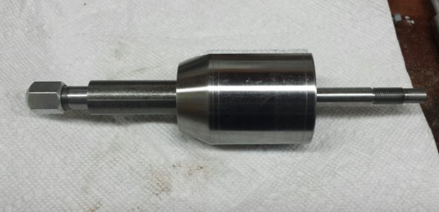
Made a new, longer spindle. Spent a lot of time chasing zeroes, and got the tailstock of the lathe adjusted to OCD level accuracy. The DTI got a workout on this part. I have some video, but my camcorder delights in loosing its tiny mind at random. I have to edit it all together.
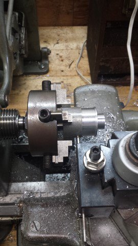
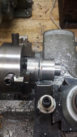
Still to be made is an arbor for the 3" wheels, but I have to grind an internal threading tool for that. The portion behind the collet nut is unfinished because I want to turn it down at the same time as the arbor. All of the threading was single-point threaded on the lathe, with the workpiece between centers. 3/8x24 for the retaining nut that goes on the right hand side, 1/2x28 for the rotozip collet nut.

Still on the todo list is the arbor, two pulleys, and a mount for the motor.

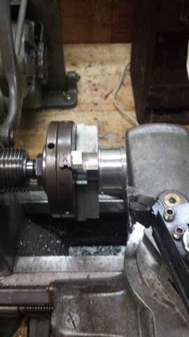
Here's where it's at so far.tmp_14583-2015-07-20 08.27.1056375274.jpg
 
Absolutely no progress lately. I've been busy with family issues.

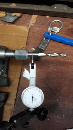
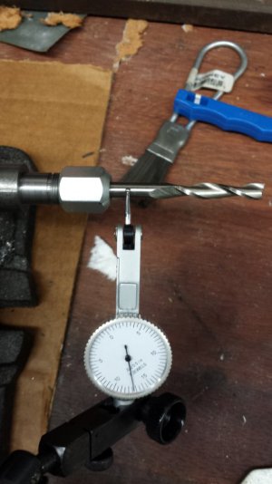
I was curious about the runout of my home-made toolpost grinder, so I grabbed the grinder housing by the tab in my knockoff Kurt vise, installed a spacer on the spindle shank so I could tension the spindle, then chucked up a 1/4" two flute HSS endmill so I could check the runout of my home-made spindle.

It's important to note that the bore and internal taper that the collet seats against were cut after I dialed in the workpiece in the 4 jaw chuck. I chased zeroes for quite awhile before I was satisfied. I called it good when I could see moderate hand pressure on the chuck body causing deflection. I believe I was accurate about to the limit of the 1945 SB9A lathe. Also, I'm not sure how much runout is caused by the taper on the collet nut. Rotozip collets are tapered on both ends.

All in all, I'm satisfied with it. I think it's passable accuracy for a toolpost grinder. Especially something home-made. The runout of the spindle bore is a tiny bit less, but I can't reach far enough inside the bore to check the rear taper.
20150726_184651.jpg
20150726_184705.jpg

A touch more than .0015" runout. I don't think making another collet nut would help much, but it would be good practice for internal single point threading.
This project isn't over, but it'll be on hold for two weeks or so.
 
Hi
Nice work, did you do a video.
The runout is not important if you true the grinding wheel, after set on the lathe. is it ?????

jeff
 
I love this design. I may borrow it to make one ( if I get well enough to get back in the shop :( ). This project is really nice and one that is needed often. Very good work.
 
I do need to get back to work on this. Haven't been in the shop to work since the end of July, just too much going on. I need to pick up a vacuum cleaner belt before I can move on with this project. I might get some work done on it this Saturday, though.

I still need to figure a way to true the grinding wheel once it's mounted. Need to buy a diamond tipped dressing tool first, though. I used to have a carborundum dressing stick, looked like a screwdriver, but loaned it to a friend and never saw it again. It was handy, and did a great job freshening up the wheels on my bench grinder.

I have some Norton cup wheels that I'd like to use on this, but have to make an arbor to do so. I also have a dozen 3" NOS carborundum brand wheels with a 1/2" bore. Those should work nicely. A side project to this is a fixture to hold in the 4 jaw chuck to allow me to use the lathe as a tool grinder.
 
A bit more work on this, only a little bit. Still lots of family stuff going on, none of it good. Got in some shop time to help put my mind at ease.

Started with a nice big chunk of aluminum bar stock. It's crapaloy, gummier than 6061, but still turned decently.
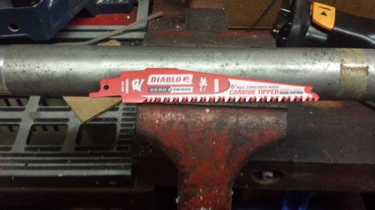
Decided to try out a carbide tipped blade on the sawzall to. It actually cut very nicely, but I need to either buy a bandsaw or build a power hacksaw. :/
20150913_115225.jpg

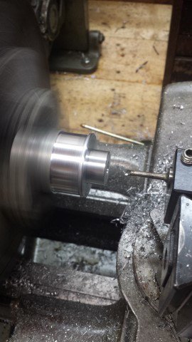
Once I had hacked off a chunk, I grabbed it in the 4 jaw and set about making it look like a pulley. IE, removed everything that wasn't pulley-like. No dimensions, just seat of the pants.
20150913_131336.jpg

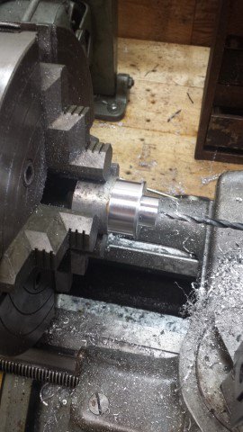
Drilled a hole, then got out a teeny tiny boring bar and had at it.

20150913_133911.jpg

Once that was done, I removed the big 4 jaw and slapped the Taig 4 jaw chuck on there. I have an MT to 3/4x16 adapter for that. It's MT2 and needs a sleeve, and I'll order the MT3 to 3/4x16 once my hobby funds aren't depleted.
The lathe looks a bit silly with that tiny chuck on there, but it works just dandy. The task with that setup? Parting off.

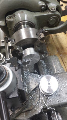
Yep. Parting off. Deep parting, lots of stickout, in gummy aluminum. The key is to indicate the tool holder so that you're as close to perfectly perpendicular to the spindle as possible.

20150913_140540.jpg

Getting there.....
20150913_141217.jpg

All done. No chatter, no problems, no issues. I ran the lathe in it's slowest backgear speed, used WD40 as lubricant, and cleared the chips once in awhile. Steady, consistent feed is the key. You want the tool to cut, not rub, but you can't crowd it too much either.
20150913_141305.jpg


Swapped for the 3 jaw chuck (soft aluminum jaws, won't mar the workpiece, but has about .003 runout, I should have bored the jaws but didn't think to...)
And took care of the other end.
20150913_142037.jpg

That's it for now. I still need to drill and tap for a set screw in the shoulder of the pulley, and make the much smaller pulley for the grinder's spindle. I still need to bodge up a quick & dirty motor mount to see if the little motor I chose for this has the oomph to run the grinder, or if I need to find something a bit beefier.

More progress to come, but I don't know when.
 
Hey ogberi, I have a multi ribbed belt off a treadmill that you can have if it fits. Let me know and I'll dig it out of the junk and measure it. Pretty sure I still have the large plastic pulley too.
 
Hi All,

Epic Fail.
o_O

The induction motor I started out with wasn't ballsy enough to keep the spindle speed up, so I tried two different DC motors utilizing the DC speed control from my Atlas horizontal mill.

Second motor did the trick, spun the spindle up to about 8K RPM, which is good for a small 1/8" shanked grinding stone.

It left a *beautiful* finish on some turned stock, but after about 4-5 minutes at that RPM, both bearings thoroughly crapped the bed. The first warning was a sudden howl and the stone wobbled the tiniest bit, then a split second later both bearings came un-stuck internally and the motor threw the belt. Where before the spindle turned buttery smooth, now it chunks and grinds and barely turns.

So, the whole mess goes in the 'aww, crap, maybe there's something useful in here' tote. Minus the DC motor. That went back in the cabinet, because there's nothing wrong with it.

Soooo...... I sat down, cracked a beer, and lit a stogie. And stared at the whole sorry mess.

Here's my new thought.

I have my Taig lathe headstock. Right now it's serving as a vertical head on the Atlas mill. Being that it mounts on a 30 degree dovetail surface (and I have a 30 degree dovetail cutter), I think it may be possible to machine a plate/mount combo that replaces my QCTP to allow me to use that spindle assembly as a toolpost grinder. Not a QCTP mountable deal, as the recently-deceased one is, but still useful. There are T-slots all over that spindle housing, so I'm pretty sure I can dream up something from the scrap pile for it.

So, this project has had a thoroughly irritating setback, but it ain't over. I intend to build a toolpost grinder, and I will. I have the need for one to get my 3 jaw chuck back into usable shape, so dang it, I gotta figure something out.
 
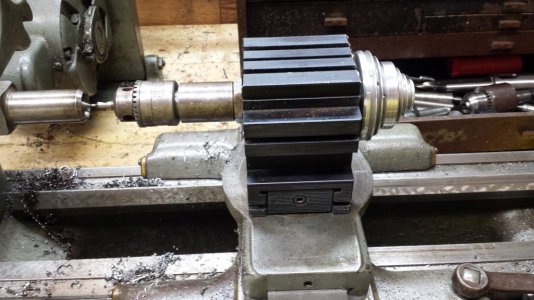
So, while nursing both a beer and a cigar along, I removed the compound from the South Bend and set the Taig headstock on there. Frowned, then removed the 4 jaw chuck, and slapped in a dead center. Put a drill chuck & center drill on the Taig spindle, and moved them up to each other. A split second later, I was digging through the scrap bin looking for a particular piece of aluminum plate I'd tossed in there awhile back. A big chunky bolt sacrificed it's head to the cause, some mill work, some lathe work, another cigar (but no more beer) and I have this.

20151018_201016.jpg

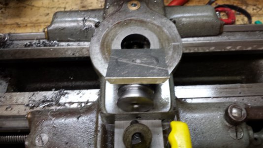
It's held down by the plate, with some 45 degree dovetails cut in it. I turned a suitable replica of the tapered knob that is on the bottom of the compound, drilled and tapped it, and bolted the plate to it.

20151018_201213.jpg

There is a spigot on top of the dovetailed knob, and a recess in the plate. That locates them together nicely. I slip the dovetailed plate into the Taig headstock, and tighten it down. Then, install it in on the cross slide,
set the desired angle, and tighten the set screws for the compound down.

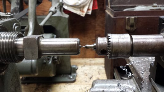
How close is it? Insanely.
20151018_201032.jpg

No shims. Everything is tight. It's a teeny-tiny hair below center. Enough that I'm not worried about it. If need be, I think a doubled over piece of foil under each side of the Taig headstock (between the headstock and cross slide) will do it.

Next up - A motor mount. I got a nice 1/4 hp 3600 rpm motor up and running, and turned a steel pulley for it to utilize a flat belt (vacuum cleaner belt, actually) Given that the headstock is covered in T slots,
I don't think it will be a difficult thing to whip up.

So, depending on how much time I have this week, I may be able to get it up and running by this weekend.

It's nice to have something go right for a change.
 
Back
Top