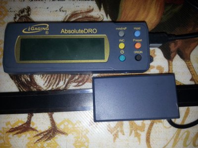
Touch Dro Fix For Igaging Absolute Dro Scales (i Hope)

Hi JPigg55
I have the same scales as you (non Plus version). Have just ordered the MSP430 boards also have plenty of Nano boards. Am hoping this will work out. BTW I cut the USB plugs off and I have two different colour combinations black red brown white green and black red blue yellow green.
Rod
 
Been a while since I last posted progress.
Not much to report. Brian Quinn contacted Scott Shumate at Shumatech. He noticed something on the O-scope trace that led Brian to think the Absolute scales have 2 read heads with an offset to cover transitions between strips. This would make the reading very stable eliminating a lot of the lower number jumping.
Problem now is figuring out how the display unit combines/interprets the 2 separate words from the read heads and outputs a single number position.
I shipped a scale and display to Yuriy as well it should be there in a day or so.
Once he has a chance to play with it, hopefully him and Brian can figure this puzzle out.
JPigg55,
I got your scale today. Brian was right, this is a completely different animal. Even the pin functions are different. Unlike the "Plus" version, Vcc, Ground, Data and Clock pins actually make sense. Now I have to figure out what kind of ptorocol it is.
I will post details once I figure something out.
Thank you
Yuriy
 
Quick update.
Not a lot of progress yet. Brian is currently setting up to do a full scale mapping run using steppers from an old all-in-one scanner/printer he had running at 5/10,000th steps.
As I understand it, once he has the data from a full mapping run, the next step will be to determine scale segment size.
Once this data is acquired, I think it will be just a matter of matching up the scale output data to the indicated reading on the display unit in an effort to determine the algorithm the display uses to convert the scale data to a digital position indication.
Once determined, it should be just a matter of writing the sketch for the Arduino & Launchpad and coming up with a schematic for the controller build.
 
My hats off to Brian & all the other reverse engineering people that take the time to improve upon devices. I have no use for these scales ATM but it still interest me to fallow.
 
Hey all following this thread, I think Brian finally has this almost licked. As it turns out, the iGaging Absolute scale use a 3 track magnetic strip encoded for the Absolute position.
Our work schedule has made progress slow going, but appears he may have a working algorithm soon.
We believe the math of the scales has been figured out and it's just a matter of finding the constants for error correction, then writing the sketch, and building the controller.
For anyone with any suggestions, here's the information he sent me:

With the cyclic counts we've got, I figured out the basic equation:


F: XXXXXXXXX

M: +YYYYYYYY00000

C: +ZZZZZZZZ000000000

zzzzAAAABBBBXXXXX


Where X is the fine track read, Y is the medium track read, and Z is the coarse track read, B is the sum of X and Y, A is the sum of X, Y, and Z, and z is the carry of all the math.

The trailing zeroes show the shift (that's multiplication by a power of 2) that is needed to account for the number of fine tracks for the medium and coarse tracks.

The final result is the sum of all 3 numbers. Notice how the last 5 bits are all fine track.

Funny thing is, that gives us a 17 bit number, or 2^17, or 131072. I was doing calcs before on the mm scale run and came up with a largest possible value of 1310.72 mm, or 51.6".


That number will be unique and sequential for the entire run.

Pretty much the only thing left now is to find the constants for error correction. Since there are only 16 possible Medium values for every Fine, and 16 possible Coarse values for every Medium, that should make the calc fairly simple.

We could do this without error correction, but any noise on the medium and coarse tracks would be HUGELY amplified, giving a rather large and unacceptable jump every so often in the readings. There does seem to be quite a bit of noise in the coarse track.


Looks like my mission here is finally winding down. May take a while longer to get it all cleaned up, but I see a light at the end of the tunnel.


This will have the advantage of not needing any type of battery back-up to maintain scale position or lose position on power loss. One issue will be the position update rate. The scales transmit on a 10 Hz frequency making the read-out a bit laggy when moving fast. Once the constants are found for error correction, the code should make the output stable like the OEM display are with no jumping around, but if used with fast feed rates, will require stopping or slowing down to come in to final position without overshoot.

I have a copy of the Excel spreadsheet with all the scale data for anyone wanting a copy, just shoot me a PM.
 
Any updates on this? I've had a set of "non-plus" absolute DROs on my mill for two years, and I'm waiting patiently to add touchdro.
 
Me too. I have cut the USB connectors off the scale leads in anticipation of connecting them to the board (that I built). However I think I will have to reattach them and live with the original readouts.
 
Sorry, not yet. Brian has been working on a new sketch for another scale data run for better data hopefully without the noise, but work schedule has been crazy as of late being short handed.
We thought we had it nailed down, but the scale track transitions are tossing a wrench in the works with one of the bits seemingly being used for something other than position, possibly a sign bit, but without cleaner data, having trouble nailing down which bit and how it's being used.
When sketch is finished, will do a slower run that will, hopefully, get rid of the skips and much of the noise. This should make it easier to find the offending bit.
The track segments seem to have a 1 mirco resolution and Brians set-up using the stepper from an old printer to run the scales. This time he's going to jumper in the display to get the scale binary number along with the corresponding display decimal output which should give us everything we need we hope.
 
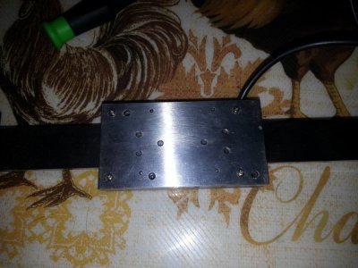
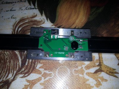
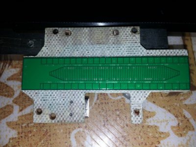
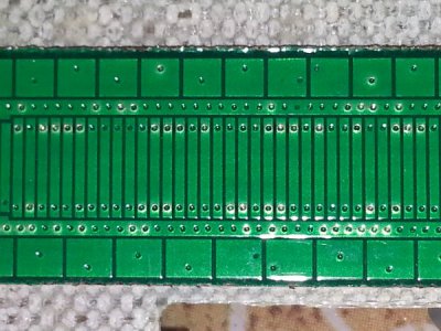
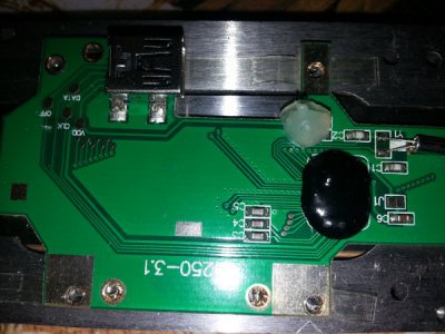
Not a lot of progress, but after getting frustrated with the data, I took apart one of the read heads to see if that might give a clue.
Here's the pictures of what's inside for those interested or if anyone is familiar with this type.

20160714_182545.jpg 20160714_182910.jpg 20160714_183124.jpg 20160714_183149.jpg 20160714_183305.jpg 20160714_184224.jpg
 
Back
Top