Tramming and round column mills

Bruce Billett

Registered
Registered
Joined
Sep 17, 2020
Messages
54
Does anyone have any experience with using optics for either tramming a tool or returning a round column tool to the proper position after moving the head?
I an rather new to the machining world, although I have been hanging around a shop for the last 40 years.
Tramming to me has always been a pain getting everything set up, the T-slots in the bed and all. While trying to come up with a way to return my head to the same position, I had a thought that an autocollimator would do this very well. (used them a lot in a previous incarnation.) I was unable to lactate one both small enough and within my budget. It did however strike me that it might be a perfect way to tram a mill/drill/lathe tailstock. Simply put the collimator down the spindle and an parallel front surface mirror on the bed/tailstock. and do the alignment. It should yield a perpendicularity within a few milli-arc seconds.
Is there anything wrong with this thought process?

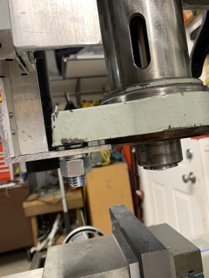
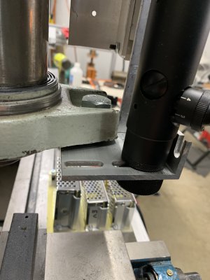
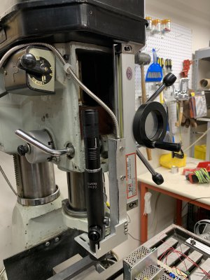
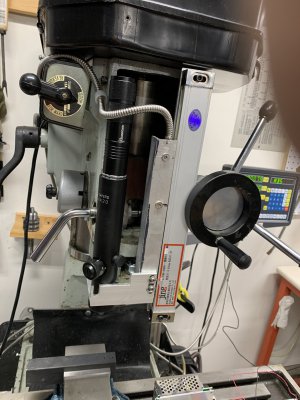
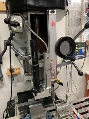
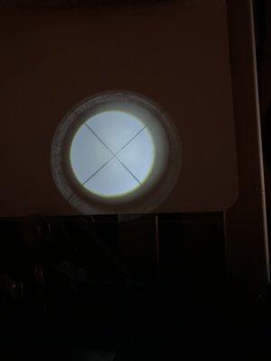
Second part, Putting my head back in alignment. After some thought I determined that this would not really address my head issue as I would not be able to put the collimator back in the spindel for the realignment. So I came on the idea of project a crosshair onto the bed. I found that a rifle scope with crosshairs and a light source placed in the viewing end would project the crosshairs on to my bed. This allowed me to get it back in very well by simply picking a spot on my bed (scribe mark way off in a corner) zeroing my DRO, moving to my scribe mark, Moving the head for whatever I needed to do, Bring the head back so my crosshairs lined up, tighten the head. Return my bed to 0-0 and I'm aligned!!!
Now I have thought that for TRUE accuery I need to align the scope so the spindle axis to be co-planner so it will work at any Z, But I am after all using a .RF mill, can't REALLY expect THAT much accuery! My tests seem to work.
Am I missing anything?

Thanks guys.
b
 
Sounds interesting. When I first got my mill/drill I thought that a scribe mark on the column with a matching mark on the head would make it easy to reposition the head. It was pointed out that a scribe mark was not accurate enough to bring the head precisely back into position. Now if I need to move the head I set up a dial indicator combined with a solid rod. Place the end of the rod and the DI against the quill and zero the DI. Move the head to do whatever and then bring the head back against the rod til the DI reads zero. Here is my set up. Quick and easy to set up and pretty much fool proof.

IMG_3922.JPG
 
I like it.
The only issue I had with something like that was that I was always bumping something and knocking the gauge out of it's initial position. Now I'm left with zero recovery options.
I'll try to get a picture of what I did posted today sometime with some more detailed instructions if you wish.
It was very inexpensive, I used a scrap 'L' bracket from my DRO install, and then went down to my local gun shop looking for a cheap scope, they found a "bad" scope in the back room, had the internal seal broken so it would fog up on cold days, Got it for $5.00, Added a 5/8" bolt washers and nut, that was the entire cost.

b
 
You might want to consider using "the longest tool" concept as described in one of the "Lazy Machinist's" videos. Basically you figure out all of the different tooling you will need for a project and then set the head height so you can change the longest tool without moving the head. Since I started doing this I have not had to move the head when doing a project.

Another thing that really helped was using ER32 collets. There is lots of wiggle room to change tooling with ER32 collets.

Bumping the magnetic base out of place is a potential problem. But not an insurmountable problem. If this happens you can get back get to position with an edge finder.
 
Attach a pencil type laser pointer to the bottom of the spindle collar with an adel clamp. Push the button to activate the laser, and make a mark on the wall where it hits. Move the head, and on return, when the laser hits the mark, you have it back in position.

The laser spot will be fuzzy, but having the mark off by 1/16" over 6' is really about as accurate as we'll ever get.

You could even modify your rifle scope to do the same thing.
 
The laser spot on the wall will only work if your mill/drill can not move. Like me many of us have their machines on wheels so they can be moved if needed.
 
Well boys and girls here it is. My latest attempt to return my mill head to its origin after moving it.
In Return site, you see the reticle I project from the scope to the bed. I put a piece of white plastic on the bed to enhance the image. Couldn't capture it in the bed proper. The rest of the pictures are just different angles and settings of the mill showing the mounting. It is up out of the way for most things and also gave me a place to mount my Z axis DRO. my existing sensor failed as I started this project and I was underwhelmed with my first attempt. Using an 'L' bracket from the sensor, I mounted it as shown. I removed and discarded the Z stop from the head. Never found any use for it other than OK stop now your halfway thru the bed! Using the mounting hole in the spindle collar I punched a hole in the 'L' bracket to accept a 5/8" bolt and used it to mount the bracket. Market out a hole for the scope. This scope has an eye piece that screws out for focusing and a locking ring to hold it in place. I used that as my mount for the scope. It is a china 4X20 Any sort of flaws in its character were not relevant as they are SO out of the field of focus I just didn't care. I eyeballed the axis alignment as the throw distance on the machine coupled with "come on man, I'm using a round column machine" made the rest just an exercise.
I then had a high brightness 4" flashlight I had robber the lens out of for another project. The O.D. of the scope and the O.D. of the flashlight are very close and I found the the flashlight just about mounted itself on the scope, this would be the end one would normally point down range.
I have no issues with the light source being off axis, after the internal optics etc. it doesn't seem to matter.
The issue of the head moving when I tightened it down I took care of with a 3" breaker bar. and a 23mm socket. This has allow me to put MORE than enough torque on the clamp bolts with just two fingers to secure the head by applying strictly DOWN force. No twisting like I would get with the factory wrench.
I keep the scope end cover on to prevent any coolant of shaving from getting on the now final optic. I have yet to make a permanent mount for the flashlight or make a dust cover for the spindel to replace the Z measurement cover Also want to find something like a 5 watt led and external power source. to make it more compact as well as give me a power source for an LED array I want to mount under the spindel to light the bed area better.
Now on to mounting my collimator. Know anyone with a 2.25" hunk of metal they can turn to hold my collimator? Can't test it without an on axis mount for it.

Enjoy Hope you like it. Any questions, PLEASE feel free to ask of tell me what I did wrong.

b
 

Attachments

  • return 2.jpg
    return 2.jpg
    1.3 MB · Views: 38
  • return 3.jpg
    return 3.jpg
    1.4 MB · Views: 37
  • return 4.jpg
    return 4.jpg
    1.7 MB · Views: 36
  • return 5.jpg
    return 5.jpg
    1.5 MB · Views: 34
  • return 7.jpg
    return 7.jpg
    1.6 MB · Views: 34
  • return site.jpg
    return site.jpg
    1.1 MB · Views: 36
  • return1.jpg
    return1.jpg
    1.5 MB · Views: 39
The laser spot on the wall will only work if your mill/drill can not move. Like me many of us have their machines on wheels so they can be moved if needed.
Yea, tried the laser thing. Beam divergence is a major headache! when I focus the beam to get a fair sized dot its reflection was so bright I couldn't make the target!! Might have even exceeded some safety standard. Worked with them just a bit. They can get nasty real quick when you break out a lens!

b
 
The laser dot on a far wall has come up as a means tramming a vise. The problem is twofold. One, the beam divergence is proportional to distance so the there is no advantage to going out a further distance. The subtended angle remains the same The secind issue for using it for column rotation is that you will need to mark a line that is parallel to the mill column.
 
Here is what I do. I will mount a dowel pin in the chuck and fully extend or retract the quill depending on which way I need to go. Then I mount a block to the table so it just touches the pin on the left side. I note the x position on the DRO or the dial. Next, I move the head. Next I adjust the quill and rotate the head so it again makes contact with the block and I tighten the head. Finally, I change the dial or DRO to the same reading as before the move. This gets me to within a few thousandths. If I need to be more accurate, I use an edge finder to re-reference the x axis. Because the y axis is essentially perpendicular to the head rotation, it is virtually unchanged.
 
Back
Top