Thank you Charles and RJ for your detailed responses, it’s really helpful.
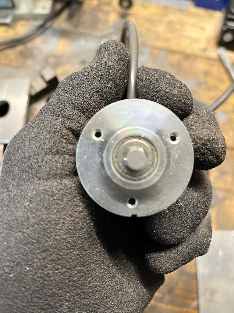
I decided to tried measuring the distance between the holes and using the bolt hole pattern on my DRO. I used the little machine shop calculator to work out the diameter of the bolt hole diameter and plugged the values in to my DRO BHP function. It was clear that something had gone wrong as the X,Y coords it gave me weren’t even close to the pattern needed. I then used the Bolt Circle Calculator on LMS and got the correct X/Y coords. After drilling the holes, they were a little off. Even though I’d measured everything several times and taken the average measurement, I’d obviously done something wrong. Measurements taken again, second attempt was much closer.
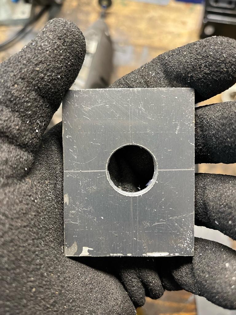
(Please ignore the bad state of the bracket at the moment, the bolt hole pattern was going to be the hardest part for me, so I wanted to get that done before cleaning everything else up)
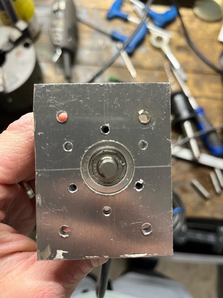
Still not perfect, but close enough for this job. I need some more practice on my measuring, but I’m really happy to have a new skill.
Now for the DRO - I think I need an end angle set (in this case to 240) in order to get proper values. Otherwise, if I set it to 360 or 0, I get no Y coordinates. I’ll dig up the manual for the DRO and read up on it tomorrow. It’s nice to know the LMS site has all of the details to work out the coords if I need it though.
Sent from my iPhone using Tapatalk