- Joined
- Feb 5, 2015
- Messages
- 662
<!--[if gte mso 9]><xml> <w:WordDocument> <w:View>Normal</w:View> <w:Zoom>0</w:Zoom> <w unctuationKerning/> <w:ValidateAgainstSchemas/> <w:SaveIfXMLInvalid>false</w:SaveIfXMLInvalid> <w:IgnoreMixedContent>false</w:IgnoreMixedContent> <w:AlwaysShowPlaceholderText>false</w:AlwaysShowPlaceholderText> <w:Compatibility> <w:BreakWrappedTables/> <w:SnapToGridInCell/> <w:WrapTextWithPunct/> <w:UseAsianBreakRules/> <w
 ontGrowAutofit/> </w:Compatibility> <w:BrowserLevel>MicrosoftInternetExplorer4</w:BrowserLevel> </w:WordDocument> </xml><![endif]--> When I was making the ER-40 collet system for my smaller lathe, I needed to check the runout on a piece of drill rod that I was using as a mandrel. I was getting some strange results from the indicator as I rotated the rod on a pair of vee blocks. Measuring across the rod to the bottom of each vee block with a micrometer, I found that the blocks weren't consistent.
What a shock: that imported tools could be inconsistent, LOL !
Fortunately, I'd not used the cast-iron blocks for anything more critical than cross drilling a hole through a round rod and similar operations. Still, I was neglectful for not inspecting the vee blocks when I first purchased them ! Since the blocks weren't hard, the fix took only moments in the horizontal mill. This is a description of the set-up: a length of ground shafting was supported on each end by one-two-three blocks on either side of a milling vise (the shaft was NOT resting on the base of the vise).
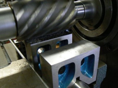
The vee blocks were then placed on the ground shaft with one edge of the block firmly held against the fixed jaw of the vise. The opposite edge was clamped by a length of 1/4 inch diameter rod which rested against the moveable vise jaw. (The purpose of the rod is to prevent the work from lifting as the vise is tightened.) Here's a photo of the set-up with a single vee block in the vise (the vise jaws had to be removed so that the vee block would fit). During the cutting operation, both vee blocks were leveled at the same time in the setup.
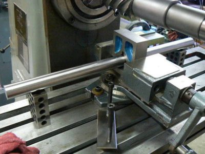
Using a four inch long slab cutter, the operation only had to remove enough material to level the two vee blocks as they rested on the ground shaft (about .002 plus another .003 to remove dings and burrs, producing a clean cut). The 2-1/2 diameter slab cutter was run dry at 140 RPM, making a single conventional pass across the vee blocks. The 1/4 inch rod to prevent lifting is visible in this photo.
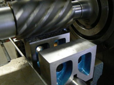
One might question why the two blocks are so far apart - wouldn't it be better if they were "stacked" side by side ? The reason is that I didn't trust the width dimension of the two vee-blocks to be consistent. The shorter of the two would not be securely clamped in the vise. So they were spaced this way so that the slight play in the movable vise jaw could compensate for any dimensional differences, clamping both parts securely.
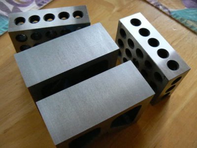
Since so little material was removed, I didn't even have to de-burr the blocks - the original manufacturer's chamfer was still visible after the cut. Here are the vee blocks posed beside the one-two-three blocks which have a ground surface. The milled surfaces of the vee blocks are almost as smooth as the ground surfaces due to the high helix of the sharp cutter.
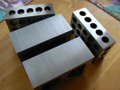
Measuring across a 1/2 drill rod to the bottom of the vee blocks indicated that they still varied by .0003 so one was carefully lapped for about a minute on a sheet of 220 grit paper placed on my surface plate. After a coat of paste wax they went back into the toolbox. (This would also have been a reasonable job on the vertical mill using a shell mill and maybe some round inserts … may have taken a few minutes longer.)
<!--[if gte mso 9]><xml> <w:LatentStyles DefLockedState="false" LatentStyleCount="156"> </w:LatentStyles> </xml><![endif]--><!--[if gte mso 10]> <style> /* Style Definitions */ table.MsoNormalTable {mso-style-name:"Table Normal"; mso-tstyle-rowband-size:0; mso-tstyle-colband-size:0; mso-style-noshow:yes; mso-style-parent:""; mso-padding-alt:0in 5.4pt 0in 5.4pt; mso-para-margin:0in; mso-para-margin-bottom:.0001pt; mso-pagination:widow-orphan; font-size:10.0pt; font-family:"Times New Roman"; mso-ansi-language:#0400; mso-fareast-language:#0400; mso-bidi-language:#0400;} </style> <![endif]-->
What a shock: that imported tools could be inconsistent, LOL !
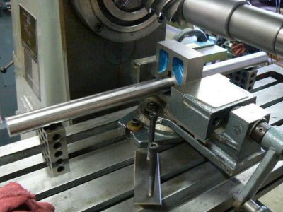
Fortunately, I'd not used the cast-iron blocks for anything more critical than cross drilling a hole through a round rod and similar operations. Still, I was neglectful for not inspecting the vee blocks when I first purchased them ! Since the blocks weren't hard, the fix took only moments in the horizontal mill. This is a description of the set-up: a length of ground shafting was supported on each end by one-two-three blocks on either side of a milling vise (the shaft was NOT resting on the base of the vise).
The vee blocks were then placed on the ground shaft with one edge of the block firmly held against the fixed jaw of the vise. The opposite edge was clamped by a length of 1/4 inch diameter rod which rested against the moveable vise jaw. (The purpose of the rod is to prevent the work from lifting as the vise is tightened.) Here's a photo of the set-up with a single vee block in the vise (the vise jaws had to be removed so that the vee block would fit). During the cutting operation, both vee blocks were leveled at the same time in the setup.

Using a four inch long slab cutter, the operation only had to remove enough material to level the two vee blocks as they rested on the ground shaft (about .002 plus another .003 to remove dings and burrs, producing a clean cut). The 2-1/2 diameter slab cutter was run dry at 140 RPM, making a single conventional pass across the vee blocks. The 1/4 inch rod to prevent lifting is visible in this photo.

One might question why the two blocks are so far apart - wouldn't it be better if they were "stacked" side by side ? The reason is that I didn't trust the width dimension of the two vee-blocks to be consistent. The shorter of the two would not be securely clamped in the vise. So they were spaced this way so that the slight play in the movable vise jaw could compensate for any dimensional differences, clamping both parts securely.
Since so little material was removed, I didn't even have to de-burr the blocks - the original manufacturer's chamfer was still visible after the cut. Here are the vee blocks posed beside the one-two-three blocks which have a ground surface. The milled surfaces of the vee blocks are almost as smooth as the ground surfaces due to the high helix of the sharp cutter.

Measuring across a 1/2 drill rod to the bottom of the vee blocks indicated that they still varied by .0003 so one was carefully lapped for about a minute on a sheet of 220 grit paper placed on my surface plate. After a coat of paste wax they went back into the toolbox. (This would also have been a reasonable job on the vertical mill using a shell mill and maybe some round inserts … may have taken a few minutes longer.)
<!--[if gte mso 9]><xml> <w:LatentStyles DefLockedState="false" LatentStyleCount="156"> </w:LatentStyles> </xml><![endif]--><!--[if gte mso 10]> <style> /* Style Definitions */ table.MsoNormalTable {mso-style-name:"Table Normal"; mso-tstyle-rowband-size:0; mso-tstyle-colband-size:0; mso-style-noshow:yes; mso-style-parent:""; mso-padding-alt:0in 5.4pt 0in 5.4pt; mso-para-margin:0in; mso-para-margin-bottom:.0001pt; mso-pagination:widow-orphan; font-size:10.0pt; font-family:"Times New Roman"; mso-ansi-language:#0400; mso-fareast-language:#0400; mso-bidi-language:#0400;} </style> <![endif]-->


Last edited:
