Trying to make sense of the threading charts

better-lathe-than-never

Registered
Registered
Joined
Sep 20, 2021
Messages
152
Figured I would post this question in a separate thread, even though it's related to my other thread on fixing the toolpost - that's also in this section.

I'm trying to understand the threading chart on my Jet BD-920N. I've studied the manual and watched a couple of good videos on this subject. With that bit of knowledge I'm trying to understand what this chart is telling me about the gears in the back of my lathe. I need someone to confirm my understanding that the "a" and "b" gears in the picture on the right are the corresponding gears on the left with the arrows - if not, I'm gonna need you to straighten that out for me first.

Given the way those gears look I suspect that my lathe came setup by the previous owner for 'mm' metric threading.

1651778183290.png
 
Last edited:
Your interpretation is correct as far as I can tell. For a novice at threading, one must understand what threading actually is. I have a Grizzly G1550 which is almost identical to the Jet BD920, so I will present my thoughts from experience rather than theory. The lead screw is a 16 pitch, 16 TPI, screw. Therefore, if you want to cut a 16 TPI thread, the cutter must move 1/16 inch for one revolution of the spindle. The gear train is adjusted, gears changed as needed, to accomplish this as needed for the particular thread.

To cut metric threads, the gears are adjusted to move the lead screw in (sub)millimeters per revolution. This is accomplished by inserting a ratio of 127:120. The 127, a prime number, is the only conversion from imperial to metric. The 120 tooth gear could be a 100 tooth as well, although the 120 tooth allows divisions by 3. There are many gear combinations that yield "almost" metric threads, many to a factor of four decimal places. With the Modulus 1 gears, 25.4 DP, the 127 tooth gear is small enough to be usable.

When calculating the gearing required for a particular thread, the quick change (QC) box must be included in the calculations. As a starter project, the 127 tooth gear is removed, forming a spacer or buffer but not a portion of the reduction gears. Using a piece of plastic, 1/2 PVC is highly recommended, as a convenient material to practice. Set the machine up for 16 TPI and rotate the spindle by hand, watching the lead screw. The depth of cut is slight, just a few thousandths for each pass.

When cutting imperial threads (16 TPI, et al) the threading dial may be used. For cutting metric threads, the half nuts are never released. The machine is stopped, the cutter is backed out, and the machine reversed beyond the starting point. I do this for both imperial and metric simply because, as an old man, muscle memory for one process is easier to remember than two.

Once you are comfortable with cutting threads, imperial or metric, the range of small threads can be easily doubled on the down side, though not shown on the threading chart. Doubling on the upper side, coarser, is not recommended for such a small machine. The slowest speed, ~130 RPM, is a little too fast for threading close to the chuck. I built a 3:1 reducer that I will post in the archives, some day. But for the novice, it is simpler to rotate the chuck by hand. Twenty some years ago, there was a move on a board dedicated to these machines that advocated several methods for this, the most notable being a small steering wheel bolted to the spindle pulley.

Cutting Left Hand threads is also no big deal. The BD920 is not equiped to reverse the lead screw, although a tumbler reverse can be easily built. There are several iterations available on the Web. It is not an advanced project, but does require a little "finagling".

.
 
Last edited:
When cutting imperial threads (16 TPI, et al) the threading dial may be used. For cutting metric threads, the half nuts are never released. The machine is stopped, the cutter is backed out, and the machine reversed beyond the starting point.
Thanks Bill -

I plan on doing exactly what you described above for practice and probably the real run too - it's fewer things to worry about for me at this stage of learning. The machine gear pics I posted above is how the machine came configured from the previous owner. I need to re-configure it for Imperial threads cutting eventually, so I'm trying to understand how to change all the gears using the chart provided. With my assumptions confirmed I can now plan my next steps - just hope I don't break any teeth doing it... I'm on a bad streak lately.

I was planning on using brass rod I found in the scrap pile and just run some threads on that. PVC is a good idea - I'll bet I have some laying around too.
 
In addition to "never release the half-nut" metric threading, there is another method::

You "pickup" (engage) the half-nut on the reverse stroke, stop, reset zero, add some cut, then cut forward, release-and-backout-and-stop as one motion. Once the lathe stops, you switch to reverse, turn the lathe on and pickup the half-nut as the number passes on threading dial. With a bit of practice, this enables threading to a shoulder, backing out the cutter (being more important than stopping the lathe) and turning the lathe off.
 
Save the brass for something useful. Good brass is hard to come by. PVC pipe is cheap, and readily available when you need it. Plus, you might get some ideas making threaded joints in PVC. The only issue with converting to imperial is removing the 127 tooth gear from the gear train. Learning to cut imperial threads is much easier, if for no more reason than using the dial. You will want to work longer pieces to start with, between the chuck and a tailstock center. Keeps the cutter away from the chuck. That does matter, a crash with either threading or power feed can cause serious damage. In that regard, there should be a plastic gear somewhere near the spindle. It is plastic strictly as sacrificial for such a situation. Once the basics are confirmed muscle memory, it can be replaced with a metal gear. It is the gear where I installed the tumbler for doing left hand threads.

A manual is available from Grizzly, https://cdn0.grizzly.com/manuals/g4000_m.pdf

The G4000 is basically the same machine as my G1550, built in mainland China instead of Taiwan. The quality is debatable, but most of the parts will fit. The chuck thread is M39 X 4 as opposed to 1-1/2 X 8. There are a few other differences, but except for screw threads really make no difference. The manual is a little better than what I got with my G1550, The gears are the same, Modulus 1, although shafts and keyways may need dressing a little. Fine sandpaper should suffice.

Mitch made a comment above that does help, once you are up to speed. I wouldn't try to decipher it until a basic concept is grasped.

.
 
Last edited:
In addition to "never release the half-nut" metric threading, there is another method::

You "pickup" (engage) the half-nut on the reverse stroke, stop, reset zero, add some cut, then cut forward, release-and-backout-and-stop as one motion. Once the lathe stops, you switch to reverse, turn the lathe on and pickup the half-nut as the number passes on threading dial. With a bit of practice, this enables threading to a shoulder, backing out the cutter (being more important than stopping the lathe) and turning the lathe off.
That sounds too complicated for me at this point. I need to crawl first... before I even walk.
 
"a" = studgear
"b" = leadscrew gear

And always be aware of the position of the "b" gear. There is a spacer there so you will have to change its position when you change between metric and imperial threads.
 
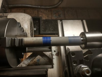
Here are my first threads on a PVC pipe - learning the basic hand operations at low speeds. Very satisfying.

Observations so far:
1) The current settings cut very find metric threads - my final threads will be much bigger (18tpi).
2) The machine doesn't stop instantly... it coasts to a stop: left or right making it more difficult to start and stop in the same spot even at these low speeds.
3) My thread cutting bit is very small (1/4'' I think) - so I may have to do another thing I'm not very good at: grind a larger tool. I'll see if I can purchase it locally from Western Tool Supply - just to eliminate that factor.

Next, I'll have to tackle the difficult part: reconfiguring the gears for Imperial thread. Dreading that part, actually....
 

Attachments

  • baby_steps.jpeg
    baby_steps.jpeg
    78 KB · Views: 119
With a 60 degree threading tool, the depth of cut is minimal on such a small machine. The largest thread I have ever cut was around 4 TPI, actually metric, but that coarse. The thread was cut on a 12 inch swing machine, in PVC plastic. Conceded, an internal thread, a female coupling. The spindle threads on both of my machines is 1-1/2 X 8 TPI. In all of these cases, I used a 1/4 inch cutter at less than 3/16 depth of cut. The 1/4 inch tool was more than sufficient. The only advantage of a larger tool is rigidity in tough to cut materials. For a novice learning on PVC plastic or brass, or even mild steel, there is no need for a larger cutter. The down side is that with a large (1/2" or larger) tool, there is also a larger tool holder which can interfere with the chuck jaws cutting close to the chuck and/or to a shoulder. Keep your dollars in your pocket. . .

Changing out the threading gears is usually a dirty operation. Having a few rags handy is helpful. And is no big deal. Just swapping a gear with a spacer. The 120/127 pair is used as an idler in imperial gears. As long as the same gear is used on both sides, it has no effect on the ratio, just a spacer. Another consideration you need to remember. There are "ranging" gears that may need to be changed as well. The "Norton" or quick change box has, if I remember correctly, 3 ranges of threads, depending on which gears are used on the leadscrew train. You mentioned a very fine metric thread, it is likely you will need to set the middle range as well.

.
 
Last edited:
Back
Top