- Joined
- Nov 7, 2019
- Messages
- 436
I need a tube bender for a tiny job so figured I'd overbuild it and use it for all sorts of things in the future.
Should be a great opportunity to practice fabricating.
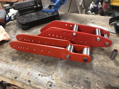
Whipped this up after googling around for inspiration.
The bottom die/mandel/whateveritis will be cut on the lathe or 3D-printed depending on what I'm trying to bend, for copper/aluminium, 3D prints will be plenty strong.
The die in the pic is tiny since I want a small-ish radius for this job, for "normal" jobs they'll be bigger.
With interchangeable dies I should be able to bend square, round tubing and maybe smaller flat bar.

Cutting whatever I have lying around the shop to size.

Of course my bandsaw decided to have a little breakdown so went with this instead.
If you ever use red dykem, remove the mill scale first ... The scribeline was almost impossible to see.
Quite a lot of time spent trying to make this with g-code on my ghetto CNC mill but it's all part of the learning experience.
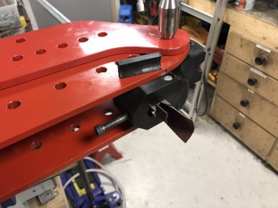
"MAIN" will be welded together with the smaller strip above, going to be a challenge to keep the warp down.
SEC used to be those really rusty pieces, did a horrible job flattening these in the mill, my setup was all wrong but now I know what not to do next time.
By being lazy, I made it take tons more time than it would've taken to do it "the right way".
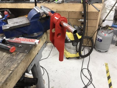
Another half-success/half-fail part, this will be the handle/lever at the top in the first pics.
At least the tube came out alright.
The side-plates had quite oval circles due to the mill having worn screws and the backlash compensation not being able to compensate enough, trying to fix this I managed to mess the part up even more with the boring head ...
Too high feed and a line of code that I missed that made it move sideways, almost needed a change of underwear afterwards...
It will all be welded together so at least I can hide my mistakes but I'll have to do some tricks to get the tube centered in the oversize holes.

Should be a great opportunity to practice fabricating.
Whipped this up after googling around for inspiration.
The bottom die/mandel/whateveritis will be cut on the lathe or 3D-printed depending on what I'm trying to bend, for copper/aluminium, 3D prints will be plenty strong.
The die in the pic is tiny since I want a small-ish radius for this job, for "normal" jobs they'll be bigger.
With interchangeable dies I should be able to bend square, round tubing and maybe smaller flat bar.
Cutting whatever I have lying around the shop to size.
Of course my bandsaw decided to have a little breakdown so went with this instead.
If you ever use red dykem, remove the mill scale first ... The scribeline was almost impossible to see.
Quite a lot of time spent trying to make this with g-code on my ghetto CNC mill but it's all part of the learning experience.
"MAIN" will be welded together with the smaller strip above, going to be a challenge to keep the warp down.
SEC used to be those really rusty pieces, did a horrible job flattening these in the mill, my setup was all wrong but now I know what not to do next time.
By being lazy, I made it take tons more time than it would've taken to do it "the right way".
Another half-success/half-fail part, this will be the handle/lever at the top in the first pics.
At least the tube came out alright.
The side-plates had quite oval circles due to the mill having worn screws and the backlash compensation not being able to compensate enough, trying to fix this I managed to mess the part up even more with the boring head ...
Too high feed and a line of code that I missed that made it move sideways, almost needed a change of underwear afterwards...
It will all be welded together so at least I can hide my mistakes but I'll have to do some tricks to get the tube centered in the oversize holes.
Last edited: