Turning a flange mount motor into a flush mount?

Remove the 1/4" flange from the new motor?


  • Total voters
    1
another suggestion is to make a thicker adapter plate , and make a 1"stub shaft extension for the motor
Yes, I have that listed above... The thing with asking about cutting off the flange is that I will have to cut pieces out of the mill mount if I don't.
That is why I was asking only about what the drawbacks that could be present if I did. Adapting plates and all, yes, I get it.. Not trying to be a carmudgeon but I didn't want this thread to turn into a what I can do to make it work. I realize those ways to mount it.

Why would you have to modify the mill in order to use the adapter plate method suggested above? I wouldn't think that would be necessary.

The downside to milling off the front of the motor is that you don't know what is back there. It looks to me that inside the ground part you'll very quickly get into the body of the motor (and end up parting the flange off instead). I'd be concerned with what is under those rectangular protrusions that they were necessary. Additionally, motors typically need the amount of mounting plate they have, otherwise they tend to torque themselves in half.

So unless you're absolutely sure that after you remove the 1/4" that not only would you not be getting into anything important on the motor, AND that the motor flange would have enough material to support it against its own torque, you'll likely just turn the motor into a paperweight.
 
I have 1/2 steel plate. After looking at the mill motor mount I am dropping the cutting off the flange idea. I would like to hear reasons why it couldn't be done tho.. Actually I guess that has been answered.
What I found on the mill mount was that it is only about 1/4" where it slides during belt adjustment so having the plate extend past that as the original motor does is required.
To avoid having to cut the mill motor mount to get the motors threaded holes to fit, I am thinking countersunk head bolts into the steel plate. Then the plate will be bolted to the original motors bolt holes. The new motors threaded holes are 7/16-14 but the feel a little loose. The bolt also only goes 3/4 of the length of the threaded hole. It is hard to see the thread pitch gauge in the holes. The bolt diameter according to NEMA for a 182TC motor is .41
If you look at the pictures, the new motor's mounting bolts are half on and half off of the mill mount when centered. The flange area of the new motor, if set on the mill only leaves about 1/2" on the mill mount. The circular cutout that the mill has is to large. I figured cutting the new motors flange off would solve a couple problems at one shot. The amount of shaft into the pulley if the new motor could flush mount would be a non issue. I agree though that because I am not positive what might be effected, I won't cut it.
So now I will have to make a 12" square of plate or aluminum. Well, steel because I have that.
 
Last edited:
I think the actual bolt size the new motor uses is 1/2-13... Now to find one in the 'stuff' lol

- I was right! Fits great!
 
Last edited:
Looking forward to seeing another Gorton making chips again :encourage:

john
 
It is your machine and motor.
if you want to modify it, then do so.
 
Capture.JPG
Because of the need to keep the motor base flat against the mounting plate, I am thinking of making a countersunk hole halfway through the 1/2" mounting plate. Then grind off the portion of the bolt sticking out after tightening the motor bolts with loctite. When the mounting plate is tightened to the mills mount, it would ensure the bolt doesn't back out or loosen. So would this countersunk hole weaken the motor bolts abilities to counter the motor torque?
I am overthinking this, I'm sure... New to motor mounting.
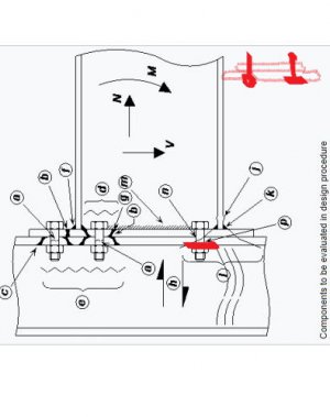
I was reading this and it brought the question to mind. https://www.steelconstruction.info/Moment_resisting_connections#Column_bases
 
I assumed that lifting the motor through a plate vs trimming the flange off would be a problem for the pulley. It does. I took the motor shaft down to 1" and am going to push the pulley bore out to 1 1/2". that way the adapter will have full engagement on the motor shaft and enough meat to hold the pulley using all 4 steps. The motor shaft only contacts half of the 2 1/2' bore length so if I didn't do this the pulleys radial load could possibly cause a problem, especially when spinning at top speed. Any thoughts on whether the 1/2" overlap will have any problems? I am going to use cross pins and loctite instead of a keyed shaft.

Which brings up a question - where can I read up on balancing the pulley and adapter in this setup?
Thanks! Dan
 
Last edited:
View attachment 328746
Because of the need to keep the motor base flat against the mounting plate, I am thinking of making a countersunk hole halfway through the 1/2" mounting plate. Then grind off the portion of the bolt sticking out after tightening the motor bolts with loctite. When the mounting plate is tightened to the mills mount, it would ensure the bolt doesn't back out or loosen. So would this countersunk hole weaken the motor bolts abilities to counter the motor torque?
I am overthinking this, I'm sure... New to motor mounting.
I was reading this and it brought the question to mind. https://www.steelconstruction.info/Moment_resisting_connections#Column_bases

While I can't evaluate the engineering of what you propose I can tell you what won't work.

"Then grind off the portion of the bolt sticking out after tightening the motor bolts with loctite."

The heat from grinding will "de-activate" loctite, that's how you get it to let go when you need to disassemble something. You'll need to apply the loctite after grinding or maybe put a small tack weld there.


John
 
Thanks, John, I decided to go with just bolting the motor to the plate, adding some plate spacers to the stock mounting bolt locations, then bolting the plate down. The extra amount of shaft exposed would not have overcome the issue in my last post. So I will go with the adapter mentioned above.
 
Back
Top