
No, the wasted spark cylinder is still 180 deg from the firing cylinder, the Hoglet is a 60 deg V twin, so spark is 60 deg apart. The engine I built is a 90deg V twin, spark is 90deg apart, hence the LV Ign unit, it has both South and North pole sensors in the pickup for the different firing plug, magnets are separated by the deg of cylinder separation.My ford EDIS based ignition system that I put in my old Mercedes is a wasted spark ignition. The plug fires TDC of the compression stoke and TDC of the exhaust stroke. Firing TDC of the exhaust stroke doesn't do many thing and the spark is just wasted. I.e. wasted spark.

-
Welcome back Guest! Did you know you can mentor other members here at H-M? If not, please check out our Relaunch of Hobby Machinist Mentoring Program!
You are using an out of date browser. It may not display this or other websites correctly.
You should upgrade or use an alternative browser.
You should upgrade or use an alternative browser.
Twin cylinder ignition module
- Thread starter Wino1442
- Start date
- Joined
- Jan 1, 2018
- Messages
- 1,160
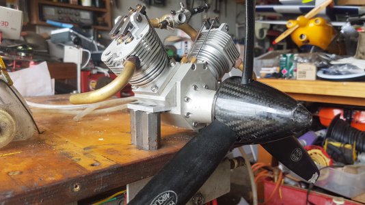
No, the wasted spark cylinder is still 180 deg from the firing cylinder, the Hoglet is a 60 deg V twin, so spark is 60 deg apart. The engine I built is a 90deg V twin, spark is 90deg apart, hence the LV Ign unit, it has both South and North pole sensors in the pickup for the different firing plug, magnets are separated by the deg of cylinder separation.
Cool engine! Thank you for the explanation. Of course your picture was worth an additional 1000 words!
2 stroke engine I assume? Actually the push rods look like they are pointed at a cam that is not integrated into the crank shaft so it must be a 4 stroke engine? Are the magnets / pickup on the cam shaft? When I put a tachometer on my lathe it read randomly until I swapped the pole on the magnet which fixed the issue. What kind of pickup is being used that differentiates between a north pole or south pole magnet?
Very interesting!
Last edited:

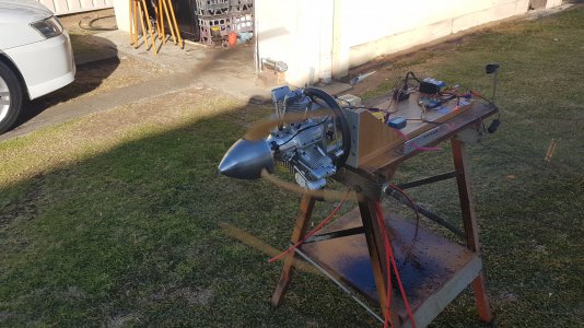
The magnets are on the prop driver at front of engine, the pickup is on the bottom of the crankcase. The pickup has both types of sensor in that pick up both North/South poles, they are a 4 wire pickup. The plug wire coming out at the CDI lable is the #1 cyl(south pole), the other is the #2 cyl(north pole)Cool engine! Thank you for the explanation. Of course your picture was worth an additional 1000 words!
What kind of pickup is being used that differentiates between a north pole or south pole magnet?
Very interesting!
Cheers
Andrew
Attachments

- Joined
- Jan 1, 2018
- Messages
- 1,160
The magnets are on the prop driver at front of engine, the pickup is on the bottom of the crankcase. The pickup has both types of sensor in that pick up both North/South poles, they are a 4 wire pickup. The plug wire coming out at the CDI lable is the #1 cyl(south pole), the other is the #2 cyl(north pole)
Cheers
Andrew
Thank you for the further information! I really like seeing the mechanics of what is in the engine! Why does the cam shaft protrude out so far? I am assuming that the cam is the long shaft coming out from the upper, larger cogged wheel?
Do you have brand new strong batteries in the ignition control box?
Do you have access to an Oscilloscope that you could use to see what signals the sensors are putting out? I think that would be the first thing I would check so you know what signals you are dealing with. If you get good strong spikes on the scope I would suspect the control box. If the signals coming from the sensors are dirty (a lot of noise) I would see what could be done to clean up the signals?
Just a thought.
Last edited:
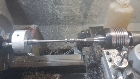
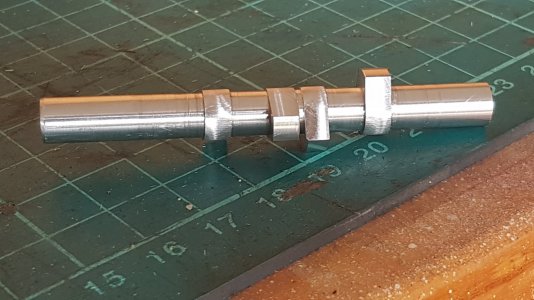
I just had not cut it down at that stage, was required to be so long for the lobe machining in the mill.Thank you for the further information! I really like seeing the mechanics of what is in the engine! Why does the cam shaft protrude out so far? I am assuming that the cam is the long shaft coming out from the upper, larger cogged wheel?
Do you have brand new strong batteries in the ignition control box?
Do you have access to an Oscilloscope that you could use to see what signals the sensors are putting out? I think that would be the first thing I would check so you know what signals you are dealing with. If you get good strong spikes on the scope I would suspect the control box. If the signals coming from the sensors are dirty (a lot of noise) I would see what could be done to clean up the signals?
Just a thought.
I use two(2) cell LiPo(8.4Vcc) 4000mah battery for the ign power.
No I have Ign test boxes that are made by Rxcel. Video is testing the pickups, first one is a single and the second one is for the LV twin box. Green is South, Red is North
Cheers
Andrew
- Joined
- Jan 1, 2018
- Messages
- 1,160
Would it be possible to post pictures of how the HAL sensor mounts to the engine and how the magnets are mounted to the crank? I would appreciate it. It would help me understand how everything fits together with those visuals.
The HAL sensor and ignition box are working fine in the video you posted. When the HAL pickup and magnets are mounted on the engine and you spin the engine by hand the tester is no longer showing the magnet signals are being picked up?
Would it be productive to mount the magnets on a wooden dowel, chuck the dowel in a drill and test the pickup with the spinning magnets? I am just throwing out some brain storming ideas, I don't know if they will be helpful or not.
Did the magnets you are using come with the HAL pickup / ignition box? They look like they are neodymium magnets? Is it possible the magnets a too strong causing overlapping magnetic fields that are interfering with each other? Again, just tossing out ideas, not necessarily good ideas.
If you remove one magnet from the engine and leave the other magnet does the ignition box pickup the one magnetic better?
Cheers Michael.
Last edited:
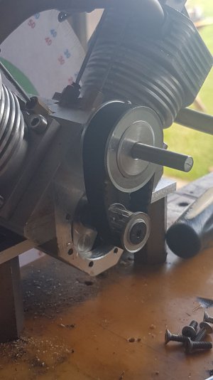
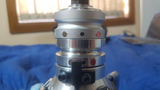
The magnets have to be mounted in a non-ferris metal, you drill the hole use Loctite and a couple of small center pops. The magnets that I use come with the Ign unit as bought. Pic shows the mounting and magnets from a Saito FG90-R3 that I have been setting up. Upper driver(flat finish) is the correct spacing for the magnets for the triple.
Cheers
Andrew
Cheers
Andrew
Attachments
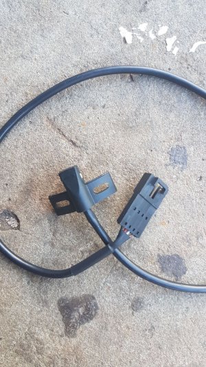
Hi all....I am having trouble with an electronic ignition module that I bought for a twin cylinder IC engine ( Hoglet) I built. The module I have is from CDI Rcexl model:A-02 ver.2. It also has a small sticker on the side of the unit that say "3W". I have attached photos to this post so you can see exactly which unit I have.
There are a couple of issues I have noticed with this.
The first one is that it appears to be that spark plug sockets are too deep..I am using NGK CM-6 spark plugs and the unit I bought is supposed to be for use with these spark plugs. I ended up removing a wire clip/ring that's at the end of the socket and that seems like it allows me push them deeper onto to the spark plug, but it takes some effort to push them on, which I think it shouldn't be so much effort to get them to stay on the plugs.
When I put power to it ( 12 volts) and when I pass a magnet over the hall sensor both spark plugs fire at the same time. I am using two magnets, one North Pole and one South Pole alternately. Sometimes the unit won't fire the spark plugs at all. I run the magnets directly on the hall sensor so I don't think it's too much distance between the magnets and the sensor.
So...I'm wondering if I even have the correct unit. If it appears to you all that I have the correct module then maybe someone could point me in the right direction as to how to make it run properly...or maybe this is a defective unit.
I'm kind of at a loss here so any help you could give me would be greatly appreciated. Thanks
Don’t throw that 3W ignition away. Please……..
- Joined
- Feb 2, 2014
- Messages
- 1,068
I thought that this may be of interest and clear things up a little.
I built a 5 cylinder redial using their module.
I have been thinking about your build of the Hoglet.
Since the cylinders are not 180 degrees apart it would seem that you would need 3 magnets 2 south for the firing and 1 north for the reset function.
I may be wrong just wondering.
Ray
I built a 5 cylinder redial using their module.
I have been thinking about your build of the Hoglet.
Since the cylinders are not 180 degrees apart it would seem that you would need 3 magnets 2 south for the firing and 1 north for the reset function.
I may be wrong just wondering.
Ray