Upgrades to my Logan 957

mhguy

Active User
Registered
Joined
Dec 10, 2013
Messages
35
Hi,

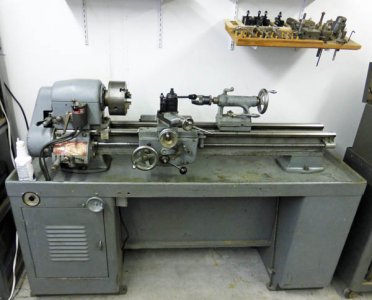
I thought I would start a thread on some upgrades I have done and am doing to my 11 inch Logan 957 lathe. I am not doing a restoration it as it is in generally good mechanical condition (although my last cleaning did a real number on the lathe's paint. I need to address that soon!) I am trying to modernize it to allow me to get better accuracy and make it easier to use, and almost as important, check off an item on my bucket list.

My dad bought this lathe in 1965 when it was about 8 years old. Sadly he passed away about 3 years later and I inherited it.


This is the Logan 957 lathe I am making these upgrades to.
lathe.jpg


I added a quick change tool post and I am adding iGaging DROs, totally changing the mechanical drive between the motor and the spindle, adding a VFD and new motor, and adding a MachTach tachometer.

I decided to use iGaging DROs on the carriage and the cross slide, as I blew my budget adding a DroPros DRO to my mill recently. Davidh, on this forum, has a great price on both iGaging and Accu-Remote DRO scales.

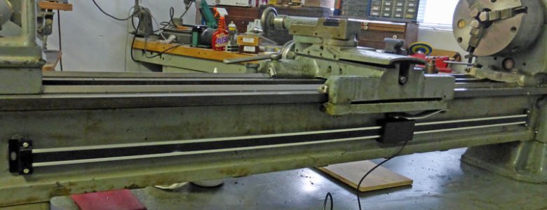
To check things out, I mounted a 36 in. scale on the back of the bed using magnets retrieved from obsolete computer hard drives. I just snapped the magnets to the end brackets and placed it on the cast iron bed. It held remarkably well! I made a simple sheet aluminum bracket between an existing bolt on the carriage and the DRO head. I had a working Z axis DRO. It was very stable and accurate, and never slipped or moved on the magnets while I used it in this temporary condition.


The 36 inch scale fits the side of the bed perfectly. The magnets are holding it tight.
422ZAxisScale.jpg


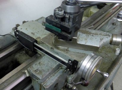
The cross slide was a totally different matter! The only place I saw I could readily mount the scale was on the spindle side with the read head between the rails, tied to the carriage. Again I tried magnets. The front mounted solidly on a machined side of the cross slide, but the rear had to stick to about a 1/4 inch wide section of the tail on the rough casting. Also the read head would crash into the chuck if I got careless (fortunately, I didn't). I found, using the magnets, they would build up a huge ball of chips when I machined steel or iron. I also noticed pock marks on the read head from hot chips hitting it. Good try, but no cigar!


The X scale just did not work on the left side of the cross slide. The gib screws would have
interfered on the right side.
838TempCrossSlideScale.jpg


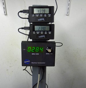
I temporarily mounted the displays on a piece of steel attached to the rear of the headstock,
letting the built in magnets hold them. I also mounted my MachTach here.
602TempDROMount.jpg


I then went ahead and permanently mounted the Z scale, removing the magnets and using 10-24 SHCS tapped into the bed casting.

After a lot of thought, I decided to mount the cross slide scale on the tailstock side to the rear of the carriage. By moving it to the rear, I avoided most of the gib screws and would keep things out of the way of most of the swarf and oil. I set up the cross slide in the mill and aligned it using a piece of drill rod clamped to the non-gib dovetail. I then took off about .050 to clean up the rough casting. I mounted an aluminum strip and mounted the scale to it. An aluminum bracket between the head and the carriage completed that mounting.


After machining a true mounting surface on the side of the cross slide, I fastened a bar of aluminum.
To this bar I mounted the X axis DRO scale and attached the read head to the carriage.
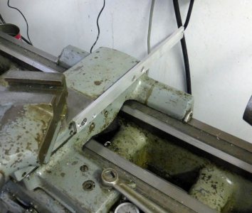
843CrossSlideScaleMount.jpg


I had to provide a clearance hole for one gib screw and taper the end of the aluminum backing
plate slightly to allow a hex key access to lock the compound.
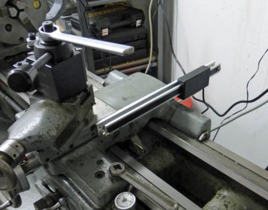
846CrossSlideScale.jpg


At the same time I was working on the DROs, I bought a MachTach and built it. I chose to use an IR reflective pickup located on the spindle at the left end of the headstock. I temporarily mounted the display unit under the DRO readouts.


I wrapped the spindle with electrical tape, then placed 6 reflective strips equally spaced around
it. The IR opto-sensor mounted to two existing tapped holes.
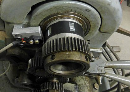
601TachSensor.jpg


That completed the first phase up the upgrade.

Next I attacked the spindle drive. Shortly after inheriting the lathe, I changed the drive to a split hub pulley variable speed system. The pulley was one I found in the Grainger catalog. It has been working pretty well for about 45 years, but it is noisy and quite inefficient. It grabs the belts so hard, I have a hard time turning the chuck by hand.

I started hearing a high pitch squeal which I traced to the pulley end of the motor. I pulled the motor and opened it up and the shaft end bearing was very rough. I worked some 10 wt spindle oil past the shields and got it running fairly smoothly and put it all back together. I am going to need to do something with the motor pretty soon! I think this whole motor/drive assembly is history!


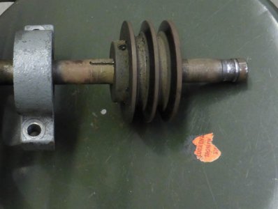
This is the variable speed pulley I installed somewhere around 1970 and it's been doing OK
but it is time for it to go! It's really ugly down here!
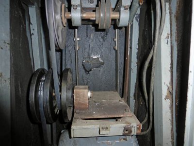
605VariDrive.jpg

I'll continue this thread soon.

Dick

lathe.jpg 422ZAxisScale.jpg 838TempCrossSlideScale.jpg 602TempDROMount.jpg 843CrossSlideScaleMount.jpg 846CrossSlideScale.jpg 601TachSensor.jpg 605VariDrive.jpg
 
After completing the DRO scale installation and the installation of the MachTach, the drive was the next area to examine.

Just a note of full disclosure: I have been doing this work over the last couple of months and am still finishing it up. To simplify writing about it I some of what I talk about is as if it is happening now instead of several weeks ago.

I decided the motor and drive pulley had to go. They had served a long and useful life, but it's VFD time!

I am sure that the pulleys and their mounting shelves which were in place when I inherited the lathe were not stock Logan. The motor mounting shelf was cast and I'm sure was original, but the next two shelves above it were weldments, and all 3 were mounted on a welded framework at the back of the drive bay. I am assuming my dad made these changes, but I'm not certain. I really cannot figure out what the original configuration was. All the pictures I have found on-line of similar lathes show components mounted to the vertical frame members, but my frame has no mounting holes in it.

When I originally installed the split pulley system, I moved the rear mounting frame to the right to make room for all the parts.

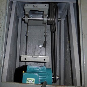
I now have removed the motor and the split pulley system

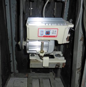
As an experiment, I decided to mount an industrial sewing machine motor I had bought to experiment with in my shop. It's destined to end up on my drill press, but I decided to try it on my lathe. It was really easy! The center shelf has a lever and lead screw to raise and lower it for changing the variable pulley. I mounted the motor on that shelf using tapped holes that lined up with wide slots in the motor base. Then by cranking the speed handle I was able to raise and lower the motor to tighten a v-belt to the large pulley which I had moved to the top shaft.

The motor is a brushless Consew CS1000 and is rated at 3/4 HP with a speed of from about 100 rpm to 4500. I'm sure it is a multi-phase motor with a custom VFD built in. I replaced a spring lever opto-coupler speed control with a potentiometer for my use.


The little sewing motor fits right in with no new holes.
618SewingMotor.jpg

I am amazed at what this little (it really is small) can do. With the speed set as low as it would go in direct drive, I could not stop it by pressing on my 6 1/2 in chuck as hard as I could with my hand. It will drive the spindle from about 35 to about 1100 RPM in direct drive, and 1/6th of that in back gear by just turning the pot. I never intended for this motor to stay on my lathe, but it assured me that I want a VFD! Actually this motor is headed for my drill press.

Even if I decided that I want this motor on my lathe, there are a couple of downsides. One is that the only provision to start and stop is by turning the pot to zero. In its sewing machine use, the operator uses a treadle to start and stop and vary the speed. You cannot set a speed and then start and stop as needed. That alone is a deal killer on my lathe. If you have the speed set very far above minimum and try to control it with the power switch, you will receive an error code on the display. You then have to turn the pot to zero and back up to your speed to work.

The other problem is that to reverse it you press one of the two buttons on the control box until you enter the menu. You then step through the menu items to the number that represents direction. You manipulate the buttons to the direction you want and wait 5 seconds for the menu to drop out. No power tapping that way!

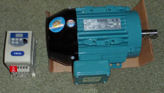
OK, enough playing around. I ordered a 1 HP 3 phase motor and Teco VFD from dealerselectric.com and it arrived very quickly. It is beautiful!


My new motor and VFD sit for me to admire on my living room floor.
modsVFDMotor.jpg


Now I have to decide just how I am going to install the motor. I am not driving it through the variable speed pulley! I could just mount the motor on the bottom shelf and run a belt to the top shelf, similar to the way I used the sewing motor. I really want to have a choice of ratios to select from, so I think setting up cone pulleys is the way to to.

Fortunately, being a thing-saver, I still have the original step pulleys that were on the lathe when I got it. One thing I am sure of is that this lathe came from the Logan factory as an all v-belt drive lathe. There are no flat belts. I am essentially redesigning the drive, as I have no recollection of how it was when I received it. My CAD program is great for this type of work. If I'm careful entering the parts to the correct size I can be pretty well assured that all will fit when I am done

While I was designing what to put back in, I pulled all the pieces out to inspect, clean and paint them. I discovered that I had a bad bearing in one of my pillow blocks that had deeply scored the shaft under it. I ordered all new pillow blocks from Amazon (of all places) and a length of pre-keyed shafting from Enco. I found that I could not disassemble the shafts and ended up going to Harbor Freight with a 25% off coupon and came home with a 12 ton hydraulic press. After easily taking it all apart with the press I remembered why they were so tight. I had applied what at the time was called Loctite bearing retainer, but now is Loctite 680. That stuff really works! I just ordered a new bottle to use when I put it all together again.


I was really surprised to see the damage to the upper counter shaft.
680BadShaft.jpg


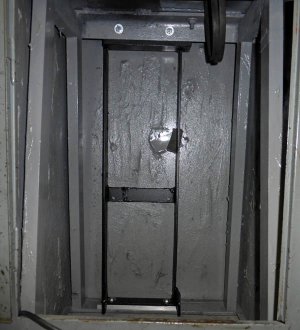
The compartment is looking a little better with paint and a clean frame reinstalled
722Comp&FramePainted.jpg


After I got things cleaned up and painted I remounted the rear frame well to the left of the position it was for the last several decades, but about an inch to the right of where it was when I got the lathe. I did this to minimize the shaft overhang to the pulley with the belts up to the spindle. After remounting all the shelves

I took my VFD and new motor to my work bench to try. After getting everything connected I applied power. I then slowly increased the speed of the motor. It was all working just like the manual said. Then all of a sudden there was a loud CLUNK and everything went dead, including my heart! After a little checking, I found I had no power to my bench and then found I had blown the GFCI. I found that it would blow each time I got the frequency up to about 13 Hz. It was too late to call the supplier, so I Googled "VFD GFCI" and received pages of how you cannot run most VFDs on GFCI circuits. The high frequency pulses in the speed control travel along the line and fool the GFCI into thinking there is a line unbalance.

I connected it to a non-GFCI outlet and everything worked fine! WHEW!

I picked the two best pillow block bearings and set up a shaft on the top shelf. I mounted the motor on the bottom shelf. I had to mill the motor mounting slots a little to match the slots in the cast motor shelf. I ran a belt directly to the top shaft to use while I was waiting for my new pillow blocks.

I absolutely love it! It is so quiet, and I can vary the speed over a wide range. I had to re-evaluate whether I really want to add the cone pulleys, but I really do want to be able to pick my basic ratio, then let the VFD work within that range. I think the quietness impressed me the most. Ever since I got the lathe there has been a deep rumble resonating from the motor to the sheet metal housing. It was just part of running the lathe. Now there is just the whir of the chuck spinning. It is wonderful!


The motor is now driving the top shaft directly. I again have a lathe!
729MotorTempInstalled.jpg


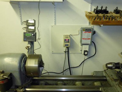
I mounted the VFD and a disconnect box on a board and hung that on the wall. I programmed my drum switch as the control to the VFD and set the pot on the VFD as my speed control. This all is until I decide just how I want to control it and buy the parts.

I now have a working VFD controlled lathe. It is great!


The VFD is mounted and connected. Most of what I have done so far is temporary.
734VFDTempInstalled.jpg

This is nothing like I expect it to look like when I am through, but for now it gets me working again.


Dick

618SewingMotor.jpg modsVFDMotor.jpg 680BadShaft.jpg 722Comp&FramePainted.jpg 729MotorTempInstalled.jpg 734VFDTempInstalled.jpg
 
Very nice looking set up. And very neat that the lathe was your fathers.
 
As soon as my pillow block bearings arrived I assembled the counter shafts on the top two shelves with the cone pulleys and set up all the belt tensions. I noticed that I had a very hard time getting a correct length belt for the motor and that it didn't have much adjustment but put off any action until later. The belt I found that did fit was one from a box of 20 to 50 year old belts. It will need to be changed out in the near future.

I can now select from four ranges for my spindle speeds giving me a range in direct drive from about 30 RPM to about 1050 RPM if I limit the VFD to 90 Hz, a conservative limit. If I allow up to 120 Hz I can get up to almost 1400 RPM. Back gear will go down to 5 RPM. According to the Logan manual the stock lathe would do from 270 to 1500 RPM in direct drive and down to 45 RPM in back gear. If I should desire to shift my speed range somewhat higher, I can always increase the size of the motor pulley, but I see no reason to do so.


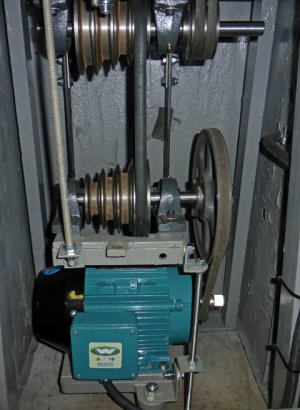
This is the finished drive with all the pulleys and belts in place.
ModsFinishedDrive.jpg


I had been planning to mount the VFD in a small plastic enclosure, but upon reviewing the specs it seems I need a larger size for proper cooling. I found a nice plastic enclosure that met their requirements and ordered it. I then realized that with such a large enclosure I could put all the disconnect, fuse, and extra outlet parts in the enclosure and make a much neater installation. My installation is starting to look more professional. The electrical outlet, now inside, is for my MachTach power supply, and possibly a light. These, along with the VFD are switched with the master ON/OFF pushbutton switch mounted on the cover.


I mounted the VFD with the face extending through the front panel. This way I have easy access
to make changes in the program and I can easily read the frequency on the display. All the high
voltage connections are protected by the case.
783VFDBox.jpg


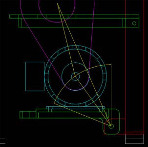
I found out quickly that to adjust the belt on the step pulleys, I had to first remove the motor belt completely. There was such a limited range of adjustment that the motor belt would bind up the shelf and prevent loosening the step pulley belt, even though I could raise and lower the motor shelf over about a 4 inch distance. It's confusing, but that is the way it works. It is time to investigate that lack of adjustment on the motor belt. I went to my CAD drawing and realized that the pivot point for the motor shelf was almost in line with the pulley centers, meaning that for a large movement of the motor, it changed the belt tension very little.


This shows the problem. As you try to adjust the motor, it just moves sideways. If you raise
the motor more than a few degrees, it starts to tighten the belt again.
modsPivotBefore.jpg


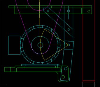
I decided that the best way to fix this was to hang the motor from the middle shelf using a pivot point that was much higher than the present one. This would allow lifting the two bottom shelves together to change the belt on the step pulleys and it would allow the maximum adjustment in belt tension for the motor.


With the pivot point even with the shaft, any movement of the motor shelf will directly
tighten or loosen the belt.
modsPivotAfter.jpg


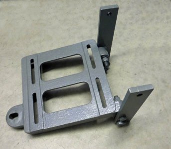
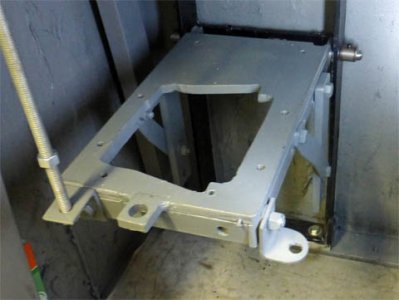
It really didn't take as much time as I had thought to build brackets up from the motor shelf and down from the middle shelf, with the pivot point where they met. Now that I have done that, I have several inches of belt length change available, and when I lift the center shelf to shift the step pulley belt there is no effect on the motor belt. I would show a picture of the assembled units here, but from the front everything looks just as it did, and I cannot get a decent shot from inside the cabinet. Instead I'll show the shelves before assembly.


New mounting brackets are attached to the motor mounting shelf.
modsLowerPivot.jpg


New support brackets are attached to the center shelf. The new motor pivot
point is where these two sets of brackets attach together.
modsCenterPivot.jpg


The VFD, pulleys, belt, and all the mechanical mounts should now be complete. Everything runs smoothly and efficiently. I can now easily turn the chuck when I need to for any reason. The lathe seems to have as much torque and power as ever, and will slip the belts before stalling the motor. This is a good thing!

Time to work on the VFD controls.

I initially set up the drum switch to control the VFD in much the same manner as it has always controlled the old motor, except now is switches very low voltage and current logic signals instead of the full motor power. I like using the drum switch, mainly because that is what I have always done. I thought I would try it the "modern" way with a spindle direction switch and start and stop push buttons.

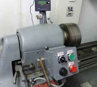
I built a control box from a plastic duplex outdoor electrical box. I bought a set of buttons and switches, and after clearing out some of the excess mounting posts and part of the conduit entrance from the box, it all fit very nicely. I mounted it on the front of the headstock where the drum switch was mounted. To space it out and angle it properly, I used a hard wood mount that attached using the drum switch mounting holes and held the box.


The new control box is installed, wired, and programmed.
834SmallControlBox.jpg


After using the controls like this for a bit, I didn't like it. It seemed awkward to reach over there to push the buttons, the box stuck out in front too far, and my chuck wrench would hit the box if I tried to use it on the front of the chuck. Enough said. On to plan B.

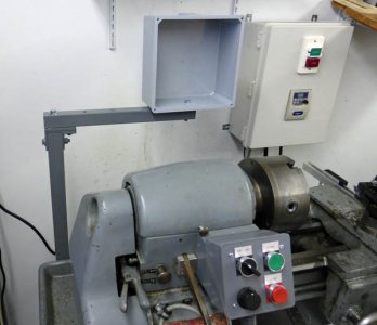
I built a post with a cross arm behind the headstock. On the end of this I mounted a plastic enclosure of 8 x 8 x 4 inches.


The newer control box is mounted on its support bar awaiting wiring.
867MountedBox.jpg


It was fun mounting the various items in this box. As received, the DRO displays can be mounted in two ways. There is a plastic plate that can be mounted to a vertical surface, then the display clips to this plate. Unfortunately, the clips are loose enough that it only take a light hit to knock it loose. The other mounting is by a pair of magnets built into the rear of the case. I used these magnets to temporarily mount them to the steel plate mounted to the rear of the headstock. The biggest problem with this mounting was that the displays could easily slide on the metal.

I am cutting close fitting holes in the front cover of the box and mounting a steel plate the correct distance behind the cover. The magnets secure the displays, and the cutouts keep them properly aligned. Also by mounting them in this manner, the cables are all inside the box.

I did not have room in this box for my full size MachTach, so I cut the board in half and stacked the two halves. I then added 16 jumpers and I had a half size MachTach. The board is very cleverly designed to do just this. If you have room for the full circuit board, the connections are already made between the logic and the display parts of the board, if you decide to stack the two halves, there are pads and holes to jumper between the two.

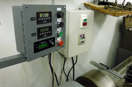
I mounted the same controls I previously had on the front of the lathe to complete the front panel. I mounted a smaller, single size outlet box on the front of the lathe with an emergency stop button. This box doesn't cause any of the problems the larger one did.

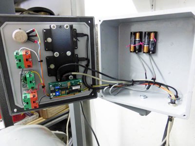
One other thing I just completed was to tap into the cables of the two DROs and bring out the power leads. I then connected them to a pair of AA battery boxes. These power the DRO instead of the small button batteries, and should last much, much longer. It turns out that the electrical draw of these displays is measured in microamps and should discharge the batteries very slowly. The actual measured current is 72 microamps while on - that's .072 milliamps, and 32 microamps while off. In spite of this I have had the original batteries of both the DROs die already. The AA batteries should last for almost the shelf life of the batteries, even if I never turn off the DROs.


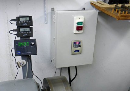
This shows the mounting of the DRO displays, behind the steel plate, the VFD control buttons,
switch, and pot, and the half size MachTach. The AA batteries supply power to the DROs. As it
would have been nearly impossible to handle the wiring with the cover loose as received, I added
a piano hinge to the left side.
FinishedControlBox.jpg


The final installation has a neat, elegant look (in my opinion)
LatheControlBox.jpg


I love using my lathe. I have instant speed control at my hand, the DROs on the two main axes are great, and the silence of its running is amazing. I am still getting used to the push button control, but it is growing on me. I'm not ready to reinstall the drum switch, but I can if I want. It is so easy to change how you control the VFD.

I love the way it all came together, although there were several cases of doing things more than once. Sometimes the re-do's were intentional temporary implementations to allow keeping the lathe usable as much as possible, sometimes they were the result of discovering that what I thought would be great, didn't really work that well. It was all fun and the results are very satisfying.

Dick

ModsFinishedDrive.jpg 783VFDBox.jpg modsPivotBefore.jpg modsPivotAfter.jpg modsLowerPivot.jpg modsCenterPivot.jpg 834SmallControlBox.jpg 867MountedBox.jpg FinishedControlBox.jpg LatheControlBox.jpg
 
Wow, Very clean setup! Great work. You have given me inspiration to make upgrades on mine. God bless.
Jon In Tucson
 
Dick,

Outstanding job........as usual. I always enjoy your well documented posts. (It may have something to do with the machines I have :whistle:)

Steve
 
Nice work. I really enjoyed your blog post about your history with PC's. I am a Field Service Engineer and service the modern servers and mainframes (now called Z sereis by IBM)

Being only 28 I enjoy reading about the early days of computing one of my favorite stories is how the Term bug gained widespread use in computer software:

The term "bug" was used in an account by computer pioneer Grace Hopper, who publicized the cause of a malfunction in an early electromechanical computer.[SUP][6][/SUP] A typical version of the story is given by this quote:[SUP][7][/SUP]
In 1946, when Hopper was released from active duty, she joined the Harvard Faculty at the Computation Laboratory where she continued her work on the Mark II and Mark III. Operators traced an error in the Mark II to amoth trapped in a relay, coining the term bug. This bug was carefully removed and taped to the log book. Stemming from the first bug, today we call errors or glitches in a program a bug.
Hopper was not actually the one who found the insect, as she readily acknowledged. The date in the log book was September 9, 1947,[SUP][8][/SUP][SUP][9][/SUP] although sometimes erroneously reported as 1945.[SUP][10][/SUP] The operators who did find it, including William "Bill" Burke, later of the Naval Weapons Laboratory, Dahlgren, Virginia,[SUP][11][/SUP] were familiar with the engineering term and, amused, kept the insect with the notation "First actual case of bug being found." Hopper loved to recount the story.[SUP][12][/SUP] This log book, complete with attached moth, is part of the collection of the Smithsonian National Museum of American History, though it is not currently on display.[SUP][9][/SUP]
While it is certain that the Harvard Mark II operators did not coin the term "bug", it has been suggested[SUP][by whom?][/SUP] that the incident contributed to the widespread use and acceptance of the term within the computer software lexicon. The related term "debug" also appears to predate its usage in computing: the Oxford English Dictionary's etymology of the word contains an attestation from 1945, in the context of aircraft engines.
 
Dick,

Outstanding job........as usual. I always enjoy your well documented posts. (It may have something to do with the machines I have :whistle:)

Steve

Thanks Steve, you do have some great machines.

Dick
 
Nice work. I really enjoyed your blog post about your history with PC's. I am a Field Service Engineer and service the modern servers and mainframes (now called Z sereis by IBM)

Being only 28 I enjoy reading about the early days of computing one of my favorite stories is how the Term bug gained widespread use in computer software:

The term "bug" was used in an account by computer pioneer Grace Hopper, who publicized the cause of a malfunction in an early electromechanical computer.[SUP][6][/SUP] A typical version of the story is given by this quote:[SUP][7][/SUP]
In 1946, when Hopper was released from active duty, she joined the Harvard Faculty at the Computation Laboratory where she continued her work on the Mark II and Mark III. Operators traced an error in the Mark II to amoth trapped in a relay, coining the term bug. This bug was carefully removed and taped to the log book. Stemming from the first bug, today we call errors or glitches in a program a bug.
Hopper was not actually the one who found the insect, as she readily acknowledged. The date in the log book was September 9, 1947,[SUP][8][/SUP][SUP][9][/SUP] although sometimes erroneously reported as 1945.[SUP][10][/SUP] The operators who did find it, including William "Bill" Burke, later of the Naval Weapons Laboratory, Dahlgren, Virginia,[SUP][11][/SUP] were familiar with the engineering term and, amused, kept the insect with the notation "First actual case of bug being found." Hopper loved to recount the story.[SUP][12][/SUP] This log book, complete with attached moth, is part of the collection of the Smithsonian National Museum of American History, though it is not currently on display.[SUP][9][/SUP]
While it is certain that the Harvard Mark II operators did not coin the term "bug", it has been suggested[SUP][by whom?][/SUP] that the incident contributed to the widespread use and acceptance of the term within the computer software lexicon. The related term "debug" also appears to predate its usage in computing: the Oxford English Dictionary's etymology of the word contains an attestation from 1945, in the context of aircraft engines.


Thanks, I'm glad you enjoyed it. I have always been heavily into computers.

I was lucky enough to see Grace Hopper (Captain Grace Hopper at the time) when she gave a talk to the San Diego Computer Society many years ago. She was quite the person!

Dick
 
Nice lathe Dick, and some changes well made. I'm sure it's going to be a pleasure to work on.
Guess you've been bitten by a "bug" of another ilk.
:allgood:

All the best.
 
Back
Top