
So I recently bought a new to me mill and it has a 5hp 220v motor on it. I purchased a VFD to power it since it uses 3 phase power. Anyone have any idea how to hook up the for/reverse swtich to the VFD and how to program it? Big ask I know. I tried to figure it out, and failed...... Any help is greatly appreciated.

-
Welcome back Guest! Did you know you can mentor other members here at H-M? If not, please check out our Relaunch of Hobby Machinist Mentoring Program!
You are using an out of date browser. It may not display this or other websites correctly.
You should upgrade or use an alternative browser.
You should upgrade or use an alternative browser.
Vevor VFD for my First Milling Machine - Help!
- Thread starter richbuss
- Start date
- Joined
- Dec 3, 2014
- Messages
- 497
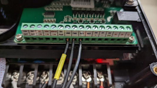
I have different VFDs but the forward and reverse are usually done the same way with these components.So I recently bought a new to me mill and it has a 5hp 220v motor on it. I purchased a VFD to power it since it uses 3 phase power. Anyone have any idea how to hook up the for/reverse swtich to the VFD and how to program it? Big ask I know. I tried to figure it out, and failed...... Any help is greatly appreciated.
The low voltage inputs usually need to be programmed as to the function of the input, but not necessarily in cheaper vfds, and then they're simply wired to your switches with a common ground.
So Input one goes to the switch and common from the switch goes to the low voltage common terminal. Input two goes to reverse switch and the other side of the switch is common and goes the low voltage common terminal. If it is a 3 way switch you only have three wires, S1 to forward, S2 to reverse, and the common to the common terminal. All are low voltage control signals.
EDIT: One your VFD the forward may be input 8, and the reverse input 9 and the common ground input 7.
- Joined
- Oct 11, 2016
- Messages
- 3,870
@richbuss Here is a link to a manual that might be your unit:
-- please verify that this is the correct manual, as models differ in their wiring diagrams.
IF this is the right diagram, then you will need to wire as in red:

I hope this helps
-- please verify that this is the correct manual, as models differ in their wiring diagrams.
IF this is the right diagram, then you will need to wire as in red:
I hope this helps
- Joined
- Apr 30, 2015
- Messages
- 11,374
Put some tape over the lower power strip terminals at least temporarily; one loose wire dropping down there and poof
It would be helpful if you could post a picture of the switch you are using
-M
It would be helpful if you could post a picture of the switch you are using
-M
Last edited:
- Joined
- Jun 12, 2014
- Messages
- 4,822
You use a rotary switch, usually 3 way maintained with two Normally Open Switch blocks. Center is STOP (both contacts open), turn one way for FORWARD, and the other way for REVERSE. Input GND connects to the input of both switches, FED connects to one switch block and REV to the other. Essentially the run command is when the switch is closed. You then need to program the VFD to tell it the source of the run command.
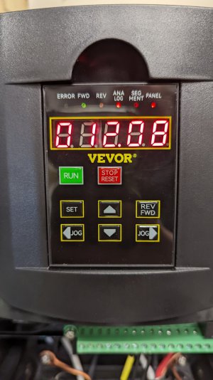
Pn 01 = 1
Pn 02 = 60 Hz
Pn 03 = 1 if you are setting the frequency from the panel with the pot (or 2 is using the buttons), if you have a mechanical Reeves drive then leave this at 60 Hz. If you have a pulley head, then get yourself an external speed pot 1, 2 or 5K and connect to the external potentiometer and set this parameter to 3.
Pn 04 = 2 this sets the source of the run commands to the inputs (i,e, FWD, REV, etc.)
Pn 05 =3
Pn 06 = 2
Pn 07 = 1
Pn 08 = 5 seconds acceleration
Pn 09 = 5 seconds deceleration
Pn 10 = 60 Hz Maximum motor freq. (can set this higher if needed, if a newer motor, something like 80)
Pn 11 = 15 Hz Minimum motor freq
Pn 12 = 60 Hz Assume this is the motor base frequency, i.e. the nameplate frequency.
Pn 13 = 0 (default)
Pn 14 = 80 Hz
The rest of the parameters I would leave the factory default. I am assuming you mill has a single speed 5 Hp motor, 4 pole, 1750 RPM at 60 Hz base speed.
A few other items. In general these type of VFD's overstate their output current, and their ability to run off of single phase which requires a more robust input section vs. a 3 phase input VFD. They often fail with high load starting, like compressors. Most people who consider buying these usually go to the next size up vs. the motor size they plan to run. There programming is very basic, and they run in what is known as V/Hz control of the motor without feedback. Most VFD's these days you need to put in the specific motor parameters and they run with feedback control, one method is called sensorlees vector control. These VFD's have a high failure rate, I have seen as high as 25%, but if they last a couple of weeks then chances are they will continue to work. The motor needle to be directly connected to the VFD terminals.
External speed pot
Switch, only use two NO switch blocks
Put some tape over the lower power strip terminals at least temporarily; one loose wire dropping down there and poof
It would be helpful if you could post a picture of the switch you are using
-M
Attachments
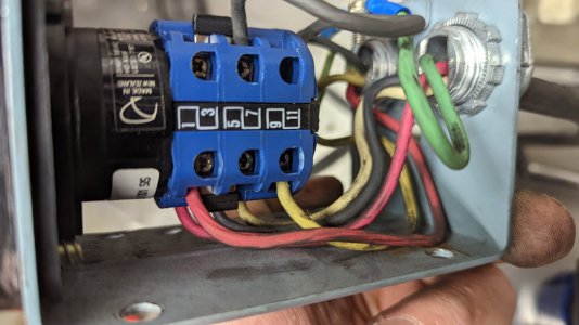
This is definetly the manual. I hooked it up like this, but I think I may have the terminals incorrect on the external switch.@richbuss Here is a link to a manual that might be your unit:
-- please verify that this is the correct manual, as models differ in their wiring diagrams.
IF this is the right diagram, then you will need to wire as in red:
View attachment 427489
I hope this helps
- Joined
- Apr 30, 2015
- Messages
- 11,374
Agreed, you most likely have the switch miswired
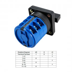
Give me a minute and I'll post a terminal chart for it
This is probably how your switch connects internally: (the Xs mean connected)
So for example you would put a jumper between say, 1 and 3 which would be your common
then 2 would be for forward and 4 would be for reverse (or vice-versa)
You might want to verify your switch matches this chart with an ohmmeter
-Mark
Attachments
Last edited:
- Joined
- Apr 30, 2015
- Messages
- 11,374
You might also want to double up contacts for lower resistance
For example:
connect 1,3,5,and 7 together which is your common
then jumper
2 and 6 = forward
4 and 8 = reverse (or vice-versa)
Switches which have been used to switch high currents tend to have higher resistance contacts from burning and arcing
which can sometimes cause unreliable VFD operation when switching low voltage control signals
Last edited:
Thank you so much on the help everyone. It turned out to be the switch wiring that I didn't get right. It's running!! Thanks again!You use a rotary switch, usually 3 way maintained with two Normally Open Switch blocks. Center is STOP (both contacts open), turn one way for FORWARD, and the other way for REVERSE. Input GND connects to the input of both switches, FED connects to one switch block and REV to the other. Essentially the run command is when the switch is closed. You then need to program the VFD to tell it the source of the run command.
Pn 01 = 1
Pn 02 = 60 Hz
Pn 03 = 1 if you are setting the frequency from the panel with the pot (or 2 is using the buttons), if you have a mechanical Reeves drive then leave this at 60 Hz. If you have a pulley head, then get yourself an external speed pot 1, 2 or 5K and connect to the external potentiometer and set this parameter to 3.
Pn 04 = 2 this sets the source of the run commands to the inputs (i,e, FWD, REV, etc.)
Pn 05 =3
Pn 06 = 2
Pn 07 = 1
Pn 08 = 5 seconds acceleration
Pn 09 = 5 seconds deceleration
Pn 10 = 60 Hz Maximum motor freq. (can set this higher if needed, if a newer motor, something like 80)
Pn 11 = 15 Hz Minimum motor freq
Pn 12 = 60 Hz Assume this is the motor base frequency, i.e. the nameplate frequency.
Pn 13 = 0 (default)
Pn 14 = 80 Hz
The rest of the parameters I would leave the factory default. I am assuming you mill has a single speed 5 Hp motor, 4 pole, 1750 RPM at 60 Hz base speed.
A few other items. In general these type of VFD's overstate their output current, and their ability to run off of single phase which requires a more robust input section vs. a 3 phase input VFD. They often fail with high load starting, like compressors. Most people who consider buying these usually go to the next size up vs. the motor size they plan to run. There programming is very basic, and they run in what is known as V/Hz control of the motor without feedback. Most VFD's these days you need to put in the specific motor parameters and they run with feedback control, one method is called sensorlees vector control. These VFD's have a high failure rate, I have seen as high as 25%, but if they last a couple of weeks then chances are they will continue to work. The motor needle to be directly connected to the VFD terminals.
External speed pot
Switch, only use two NO switch blocks