VFD build for Standard Modern 1340

@macardoso thanks for making my life easier! Yes planning on using the gears on the lathe and just tuning the speed with a pot.

Read parts of the WJ200 manual when it was slow at work. Going with the Hitachi since I can buy it from drives warehouse.
So far this is what I have:

Main panel -> Enclosure -> Power Disconnect Switch-> Breaker -> EMI filter -> Hitachi WJ200-022SF VFD -> Motor

VFD inputs/outputs:
Brake resistor
Controller
Forward/Reverse drum switch from from Apron Lever

For the front panel controls. Front panel would be run, stop, amp meter, 1k 2W pot for frequency adjustment. I dont know if I would use a jog joystick/button. Will be using a air mister so no coolant pump/control needed.

15A 2 pole breaker -> 220V to 24VDC transformer -> Ice cube relays for Run, forward, reverse (not sure if this is needed on forward/reverse if I dont use a Jog button on the control).

Might go with a wall mount enclosure so that I can house the VFD and ELS together. I can modify the back of the lathe to fit a 12x15x8 enclosure which might be too small to fit the VFD and ELS.
 
Last edited:
Side note: I thought you were supposed to use fast blow fuses so that if the motor shorts the fuse trips to protect the VFD

Or is that just a UL thing
 

Looks great to me so far!

VFD inputs/outputs:
Brake resistor
Controller
Forward/Reverse drum switch from from Apron Lever

Just curious, what is the controller? I would also just wire the start, stop, analog meter, and potentiometer to the drive directly unless it does not have sufficient I/O. How do the run/stop buttons interact with the apron start/stop lever? Or is this a hydraulic lathe where the apron lever closes a clutch?

For the front panel controls. Front panel would be run, stop, amp meter, 1k 2W pot for frequency adjustment. I dont know if I would use a jog joystick/button. Will be using a air mister so no coolant pump/control needed.

I'd probably go with a 10k pot. You are just using it as a voltage divider, so no need to draw excessive current. Jog button would be nice, especially if the VFD can be set up to run at 5% speed when you hit the button.

15A 2 pole breaker -> 220V to 24VDC transformer -> Ice cube relays for Run, forward, reverse (not sure if this is needed on forward/reverse if I dont use a Jog button on the control).

Personal preference is to use a 24VDC power supply and skip the transformer. Plus the transformer will put out 24VAC not DC. These are my favorite for home use and can be powered directly off the 240V line:


I'd put a pair of 5x20mm 1A (Bussman GMA-1-R) fuses before the PSU, probably in these holders:


Side note: I thought you were supposed to use fast blow fuses so that if the motor shorts the fuse trips to protect the VFD

Or is that just a UL thing

You are right there, I've been doing a lot of across-the-line motor starter applications the past few months where fuses are sized for the motor load. To protect the VFD, you'd select fast acting fuses. In this situation, the fuses protect the wiring to the VFD from failure if there was a line to line short in the wires or internally to the VFD. The fuses do not protect the motor - that is the job of the VFD. The VFD will have faults for motor overload, current imbalance, short circuit, and ground fault. The fast acting fuses tend to give the VFD a better chance at survival in a fault condition.

Also I'm not a code guy, so take my statements with a grain of salt. We design to code at work, but I get an independent review from a code guy before I send it out.
 
PS: Just buy the shunt resistor designed to go with your drive. You can substitute other ones, but it is just easy to get the matching unit. You have to match both ohms, power rating, and thermal properties or the drive will not like it.
 
Just curious, what is the controller? I would also just wire the start, stop, analog meter, and potentiometer to the drive directly unless it does not have sufficient I/O. How do the run/stop buttons interact with the apron start/stop lever? Or is this a hydraulic lathe where the apron lever closes a clutch?
@mksj referred to his front panel controls (start, stop, jog, coolant) as a controller in a couple other posts and it was just what stuck in my brain. I have been looking at wiring schematics he has done on precision mathews lathes and he runs the start, forward, reverse through relays so that is why I was thinking of it. Not completely sure it is needed for my setup.

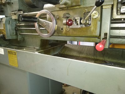
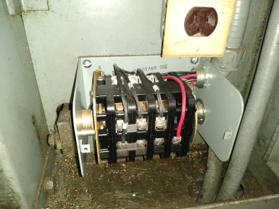
The lever on the apron seems to be mechanical from what I can see and just operates the drum switch on the back of the lathe.

carriage.jpgdrumswitch.jpg

I'd probably go with a 10k pot. You are just using it as a voltage divider, so no need to draw excessive current. Jog button would be nice, especially if the VFD can be set up to run at 5% speed when you hit the button.
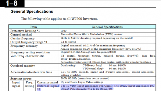
The WJ200 manual stated a 1k-2k Ohm pot:
VFDpot.png


Personal preference is to use a 24VDC power supply and skip the transformer. Plus the transformer will put out 24VAC not DC. These are my favorite for home use and can be powered directly off the 240V line:


I'd put a pair of 5x20mm 1A (Bussman GMA-1-R) fuses before the PSU, probably in these holders:

Good call! For sure just using a PSU is a better setup.

You are right there, I've been doing a lot of across-the-line motor starter applications the past few months where fuses are sized for the motor load. To protect the VFD, you'd select fast acting fuses. In this situation, the fuses protect the wiring to the VFD from failure if there was a line to line short in the wires or internally to the VFD. The fuses do not protect the motor - that is the job of the VFD. The VFD will have faults for motor overload, current imbalance, short circuit, and ground fault. The fast acting fuses tend to give the VFD a better chance at survival in a fault condition.

Also I'm not a code guy, so take my statements with a grain of salt. We design to code at work, but I get an independent review from a code guy before I send it out.
I saw another VFD setup that used fast acting fuses right after the motor rated breaker. Seems that for UL testing they use them for test purposes and just keep them in scematics due to that but in real world scenarios the VFD would fry regardless.

PS: Just buy the shunt resistor designed to go with your drive. You can substitute other ones, but it is just easy to get the matching unit. You have to match both ohms, power rating, and thermal properties or the drive will not like it.
Is the shunt resistor the same as the brake resistor?
 
@mksj referred to his front panel controls (start, stop, jog, coolant) as a controller in a couple other posts and it was just what stuck in my brain. I have been looking at wiring schematics he has done on precision mathews lathes and he runs the start, forward, reverse through relays so that is why I was thinking of it. Not completely sure it is needed for my setup.

The lever on the apron seems to be mechanical from what I can see and just operates the drum switch on the back of the lathe.

Got it. You can certainly go that route with using relay logic to build a final RUN/STOP signal to go to the VFD. I'm not sure what configuration options you have with the WJ200, but the VFD's I'm used to working with have a ton of flexibility with configuring the IO. And there is also a lot of IO to begin with.

If the WJ200 has enough IO and you can configure it to do everything you need, I would go that route, but that is me personally.

The WJ200 manual stated a 1k-2k Ohm pot:

1597321705026.png

Is the shunt resistor the same as the brake resistor?

Yeah sorry, we call them shunts at work. Same thing.
 
So a few suggestions, there are a number of variations on VFD control systems and options. The lathe's require a bit more effort for safety reasons and also integration of controls and manual brake if you have one. Most individuals opt to use the stock spindle control to operate the VFD low voltage signal controls, I see no reason why you cannot reconfigure the current drum switch to do this. I have posted suggestions on components for the VFD enclosure and what would be typical installs, this is adjunctive to the manuals. The manuals list every possible component that might be used with a A VFD, but at the end of the day, the minimum (my recommendation) would be an enclosure, power disconnect switch and braking resistor (this is outlined in my install documents). Fast acting fusing can be used, I use the CC fast acting 30A fuses, unless you are on a dedicated 30A breaker. Fusing is optional, but I install them on most of my systems, they can also protect the VFD from a reverse line surge. Other consideration is VFD's can generate a lot of RFI and EMI that can cause electrical interference. So some people like to add an electrical noise filter after the switch power input.

As far as relay control systems and design, there are a lot of options from a single 4P relay that is powered by the WJ200, to multiple relay designs that are powered by a separate 24VDC source and would be needed if you want to run coolant or need additional features. But a single 4P 24VDC relay will work and is simple. I have information on different designs, you can PM me and I can send you some recommendations. Speed pot is 1 or 2K, most people add a simple tachometer with a spindle pickup. There is no need for the current amp meter, I would replace it with a tachometer display. The current Star/Stop buttons, not sure what they do, does this model have a clutch engagement system and the motor runs continuously, does it have a foot brake? These all effect the design.
Mark
 
Thanks @mksj and @macardoso you have helped a lot!

So my idea so far is 30amp breaker in the sub panel, then 30amp motor rated breaker in the VFD enclosure, then fast acting fuses, then emi/rfi filter then VFD to motor.

I will be building a tach that will be integrated with the electronic lead screw I'm building. I was removing the amp meter and putting the ELS controller in that spot.

Was considering adding Jog feature. The carriage jog would be controlled by the ELS (not sure I'll even add it since I rarely work with long pieces). The spindle jog would be controlled by the VFD so it would need to be a three way switch.

Motor does not run continuously. Here is a video of a Standard Modern 1340:

I would like to add a foot pedal.
 
So made some progress on the VFD build finally. Modeled up the scematic and have all the components and wiring (I hope)
 
Back
Top