VFD choice for new mill

Wow, tons of good info!
Thanks, everyone for taking the time to respond. Sorry I haven’t had time to reply individually, but it’s all been helpful.

I will stick with the L510 since I have a basic grasp on what it can do, and how to tweak it. It can run as low as 6Hz and has SLV mode and built in braking.
The WJ200 would probably be my second choice.

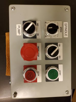
I have a control box that had been retrofitted to my lathe, with six Allen-Bradley switches/10K pot. That will be perfect to control a power-latched contactor and three-wire low V control as mksj suggests above. The lathe also provides a circuit breaker, fuse blocks and the contactor, which has a 24V coil and a transformer, so there will be no high voltage current in the control box. I will also add an EMI filter, and an auxiliary cooling fan for the machine motor which will run when the motor is operating at a low speed and prone to overheating.

Finally managed to add a photo. I can only get it in as a thumbnail link.
Anyway, I'll remove the 'spindle' and 'pump' stickers and swap the On/Off switch and Start pushbutton. So the top row will be spindle controls (speed, direction, on/off).
The bottom row will control the contactor which powers and shuts down the whole thing.
 

Attachments

  • 20200302_233147.jpg
    20200302_233147.jpg
    1.8 MB · Views: 28
Last edited:
120AC will supply a standard power strip, which will later run the power feeds, as well as a small 12VDC supply. The 12V will run an auxiliary cooling fan to boost airflow through the big motor when operating at lower speeds.
120V also runs through a two-leg C/B to a stepdown transformer which runs the 24VAC contactor coil. That supply runs through a Stop pushbutton and E Stop switch, then the momentary Start pushbutton. When the coil is energized, an aux leg of the contactor keeps the coil latched on as long as power is supplied. A power loss will shut everything down regardless of switch positions.
Two of the three power legs of the contactor control 240V power to the VFD (passing through two fast acting fuses and an EMI input filter). The same 240V/30A circuit will have a branch with an outlet for lathe power, since only one machine at a time will be used.
The VFD three phase outputs will have ferrite chokes to help reduce radiated EMI. The VFD's low voltage terminals include a relay to control the aux cooling fan, On/Off and Fwd/Rev switches, and a 5k potentiometer for speed control.
 
Not the correct way to hookup the VFD, they are not designed to be turned on/off frequently to run a machine. You want a main power switch to energize the VFD, you can use a contactor but it is not needed. When you power down a VFD you should wait at least 5 minutes before powering it back up. Frequent on/off powering will damage the VFD because the current inrush relay/resistor will fail.

You use 3 wire control to run the VFD, check the manual, it uses 3 input terminals. Power loss or on power up wil stop the machine. E-Stop breaks the connections to the control inputs, but you will still will get electronic braking.
 
replace the for/rev whit a 3 Position button and use this for start stop/for/rev.
 
Not the correct way to hookup the VFD, they are not designed to be turned on/off frequently to run a machine. You want a main power switch to energize the VFD, you can use a contactor but it is not needed. When you power down a VFD you should wait at least 5 minutes before powering it back up. Frequent on/off powering will damage the VFD because the current inrush relay/resistor will fail.

You use 3 wire control to run the VFD, check the manual, it uses 3 input terminals. Power loss or on power up wil stop the machine. E-Stop breaks the connections to the control inputs, but you will still will get electronic braking.

Thanks for taking the time to look it over, I appreciate your input!

We’re on the same page here, but I wasn’t clear about how I will use the controls. Rest assured, I won’t be turning the VFD on and off repeatedly, just at the beginning and end of a session. I’d rather have switch labels that say something like Power and Shutdown, but I couldn’t find any. Maybe I’ll try to make my own. My Start/Stop buttons will not be used as motor controls though.

True, a contactor is not required in the manual, but suggested. And the VFD does have built in power-off protection. For anyone wondering, the manual says a circuit breaker may not be used to turn the VFD on and off. So I could either buy a high voltage power switch, or use the contactor that’s already sitting on my shelf for the low price of $free.99. And, I get an additional layer of protection.

3-wire control is correct, and that is shown on the left side of my diagram. The On/Off and Fwd/Rev switches connect COM to S1 or S2, with S1 and S2 programmed for Fwd/Stop and Rev/Stop functions. And the Speed knob controls speed.

You make a great point about the benefit of having electronic braking during an emergency stop.
Initally, I was going to put the E Stop switch in series with the 3-wire circuit, but I realized that if the switch was reset (either thoughtlessly or accidentally) the VFD would see it as a Run command and start running the motor. You’d have to remember to turn the motor control Off before resetting the E Stop. Moving the E Stop to the contactor coil protects the user against a brain fart in the heat of the moment.
However! I had not considered the issue of braking. It would definitely be better to keep that capability during an emergency stop. Looking at the manual again, I see a Rapid Stop function that can be programmed for one of the switch inputs. I’ll try that out when I bench test this rig, putting the E Stop on input S2. If I get that to work (keeping protection against unintended start), that would be the way to go, so I thank you in advance.
 
Last edited:
replace the for/rev whit a 3 Position button and use this for start stop/for/rev.

Thanks for your reply!
The three position switch is more common I guess, but if you look at the way I have my two switches set up (see the left side of my diagram), they do exactly the same thing. That’s just the way I think - in steps. 1. Choose direction. 2. Turn machine on/off.

For more detail, see my reply to mksj above.
 
Last edited:
your panel have a start button for spindel .. the same button is stop spindel and it say start only? if ist only using it ist no problem,,
 
Three wire control works with momentary switches, you use your start and stop buttons to control the on/off. the reverse is a sustained switch. If running you can flip the direction switch and the mill motor will change direction w/o operating the stop/start button. Any interruption of power it goes to the stop mode. E-Stop use a NC switch block that goes open when engaged and interupts the COM input, you can also have a second E-Stop NO switch blocks the goes closed when pressed and can connect to S4 programmed as an emergency stop. The contactor is sometimes used for the power on, but requires a separate on/off switch, a transformer that is always on and additional wiring. Most VFD's have an option to not allow a VFD to restart when powered up. A 30A rotary power switch can be purchased for around $30. The manuals show all kinds additional accessories not really needed. You do not need to add a lot of complexity on a mill for basic operation.

On some of the systems I build I do more complex systems with auto-tap auto-stop/start based on quill position, maintains same direction in back gear, etc. This requires more complexity, but for basic systems I use the 3 wire as described.

3 wire control.jpg
 
Three wire control works with momentary switches, you use your start and stop buttons to control the on/off. the reverse is a sustained switch. If running you can flip the direction switch and the mill motor will change direction w/o operating the stop/start button. Any interruption of power it goes to the stop mode. E-Stop use a NC switch block that goes open when engaged and interupts the COM input, you can also have a second E-Stop NO switch blocks the goes closed when pressed and can connect to S4 programmed as an emergency stop. The contactor is sometimes used for the power on, but requires a separate on/off switch, a transformer that is always on and additional wiring. Most VFD's have an option to not allow a VFD to restart when powered up. A 30A rotary power switch can be purchased for around $30. The manuals show all kinds additional accessories not really needed. You do not need to add a lot of complexity on a mill for basic operation.

On some of the systems I build I do more complex systems with auto-tap auto-stop/start based on quill position, maintains same direction in back gear, etc. This requires more complexity, but for basic systems I use the 3 wire as described.

View attachment 316078

Okay, thanks again!
I now have a fuller understanding of 3-wire inputs. And you’ve driven me to dive into the manual some more.

It looks like you pulled that diagram from a Teco manual. For the L510, that’s page 4-35. Describes how 3-wire works.
So it looks like I’m actually talking about 2-wire, Mode1 as on page 4-33. Honestly I think the 2-wire appeals more to my primitive caveman brain. But I promise, when I bench test the wiring, I’ll try out the 3-wire method and see how I like it.

Start switch v. contactor? I compare it like this:

Start switch
- works good
- don’t have one, would cost me:
- $30 (that’s two dozen oysters around here)

Contactor
- works good too
- already have it
- Free! (trump card)

The VFD will be here in a few days. I’ll update when I wire up a test.
 
Last edited:
Back
Top