VFD setting for YL620-A 1.5kW air cooled

regpye

Registered
Registered
Joined
Jul 10, 2014
Messages
10
I have a YL620-A VFD and an air cooled 1.5kW 220 volt spindle.
I am able to make it run successfully and control the speed from the controller pot on the VFD panel.
I am using Estlcam software which has speed control built in and I have made the control board to produce the variable 0-10 volts required to control the VFD.
I can produce the 0-10 volts from the software, but am not able to get any response from the VFD using it.
I have the variable voltage 0-10 volts connected to the Gnd and the 10V connectins on the VFD, I have also tried the GND and VI1 connections (pot rotor)
I have had to do all the speed control from the VDF panel instead, although I am able to turn the spindle on and off with the software successfully.
I have tried various settings in the VFD but without success in remotely controlling the speed via software.
Does anyone on this forum have any suggestions on how to set up the settings for the remote control please?
 
I have found a section that I don't really understand and there does not seem to be enough information available in the manual.
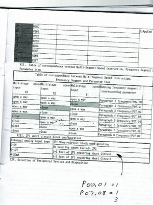
Settings indicate that I should use P00.01 = 1 and P07.08 = 1 and JP1 requires 2-3 feet short circuit (what ever that means) and no indication where to find JP1.
 

Attachments

  • YL620-A manual 1.5KW-220v.pdf
    825 KB · Views: 63
Connection for external speed control should be negative (0 V) connected to ACM and sweep voltage (positive 0-10V) to VI. It is unclear as to the internal grounding connections of ACM and DCM, but they are not connected to earth ground.

PD002 needs to be set to 1 which is the source of operating frequency set by external terminals. PD70-76 set the analog input parameters, you should be ok with the default settings to start out.
My manual shows a different terminology P00.02 is marked as reserved.
I cannot find PD70-76 in the manual or on the VFD, maybe you are referring to a different VFD?
 
Version on-line that I downloaded was different. Looking at the manual you posted, you would probably want 2 below, but then the manual is clear as mud:
1.The motor speed is controlled by the operating panel
2.Motor speed control by external terminals (Potentiometer 10K). P00.01 set to 1, P07.08 set to 3
3.Motor speed control by external terminals. P00.01 set to 1,P07.08 set to 1.

The upper an low bounds of the frequency range are set by P03.12 and P03.13.

speed inputs are COM (XGND) and AI1.
Thanks for your reply.
Yes I have tried these settings except for the P03.12 - P03.13 settings which are still set at 0 each. Maybe I should change them to 400 and 0?
Both have a note against them of "JP1 short circuit block configuration table" of which I can find no reference to.
(mud is clearer)
Another page that is not shown in this manual shows something about JP1. The pages comes from the manual supplied with the VFD and is the same as the PDF except it has a couple of extra pages. The page in question is attached.
 

Attachments

  • page-28.jpg
    page-28.jpg
    70.6 KB · Views: 55
Have no idea what they are talking about, you are just scaling the voltage output, it is also different based on the VFD model. I would contact the dealer that sold it to you.

If it works with an external speed pot to the 10V VFD input then it may be a loading issue, maybe put a voltmeter on the COM (XGND) and AI1 with everything connected and make sure the voltage is changing. One reason why it gets pretty frustrating working with these generic VFDs, the manuals tend to be very poor and no technical support.
 
I have just tried setting P03.12 =0 and P03.13 =400
The results where that the spindle would not start but it did move a little, so I increased the P03.12 = 30 and the spindle would start and run at a slow speed, maybe about 2000 RPM.
I could not get an increase in speed though, so I connected a multimeter across the GND and the 10V out of the LM358 board that produces the variable 0-10V output and under software control works OK. The VFD doesn't respond to the reference voltage.
I tried setting the P03.12 to other values and I can increase or decrease the starting speed by this setting, but the upper setting on P03.13 doesn't respond at all.
 
UPDATE: Got it working OK, mostly.
Settings P03.12 =20 (spindle will not start if much less and the lowest speed I would use would be faster anyway)
P03.13=400
After setting, shut down the VFD and restart and then it works OK.
Next problem is the speed range. Everything works fine using the speed control slider in the software up to 100%, after 100% there is no further increase in speed all the way up to 200%.
I tested the voltage out from the LM358 board and the slider shows a full range of voltages from 0 - 10 volts across most of the range, the increase in voltage after the 100% mark doesn't seem to do anything.
Learning all the time, it is interesting to work out these problems, but is also a pain at the same time.
 
Back
Top