Weird stuff happened when I plugged in a new inverter.

Inverters are diode heavy and they have zero tolerance for reversed polarity. I have a 3000w inverter that I use to runs saws and whatnot on the jobsite. It connects to my truck batts via a pair of cables with giant alligator clamps like boosting cables. I hooked it up backwards one rainy night and POOF. Blew every diode in it. After the manufacturer told me it was not field servicable I opened it up and replaced the diodes for about $ 50. You know it was easy because I could do it!
 
Well, if it wasn't popped before, it's popped now.

I read the wiring part of the manual again.
I used an ohmmeter to verify that the cord was wired properly.
I used the ohmmeter to verify that the cord connections were getting to the terminals properly.
I moved the ground from the brake negative to the third lug from the right.
I plugged in to a dedicated 30A plug and POP!

This time it popped inside the unit and the display didn't do a thing.
I smell magic smoke when I sniff it.

I might do some forensics and see what popped. I might even redo whatever popped. I've been doing that stuff for 40 years.
 
I just re read the tag under frequeency converter.
High voltage inside. Mainrained by thr weil-trained peronnnel.
WTH.
 
I just re read the tag under frequeency converter.
High voltage inside. Mainrained by thr weil-trained peronnnel.
WTH.
HA!, I thought you were just drunk typing. I didn't even catch the really bad speeling

For the warning: Once you've discharged a flyback transformer, through your body, nothing but lightning is scary.
 
I think it was a 50/50 chance you would have got it right- inside the unit the ground symbol is over to the right. Then the outside sticker shows it three positions over. What are you supposed to do?

Gotta watch it though......I think there are two grounds!

The way I read it is that terminal #6 is "FG" (frame ground or chassis) and the screw down to the right is also a ground (with the traditional ground symbol on the plastic).

-brino
 
BTW, it doesn't need the ground to work. I'm not using one on the VFD for my spindle. You can just ground the whole machine if you're concerned but for what we're building....

John
 
Gotta watch it though......I think there are two grounds!

The way I read it is that terminal #6 is "FG" (frame ground or chassis) and the screw down to the right is also a ground (with the traditional ground symbol on the plastic).

-brino
I forgot to mention that there's zero continuity between the screw to the right, or it's twin on the left, or #6.
The three are completely isolated from one another.
 
It's dead.

The autopsy complete.
First I checked to make sure I was getting proper voltage to the pins. 120v confirmed
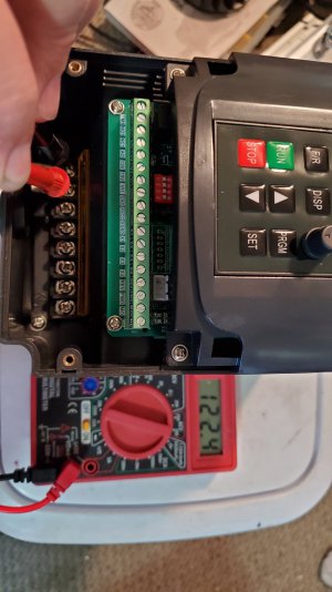


20200430_195755.jpg
I don't know what happened to the first few photos I took but I exposed the top board and inspected all the components for damage. They all appeared fine, at first.

Next I took apart the unit and removed the top board. It was pretty obvious where the pop was. The weird thing is that this is where the burn was most prominent but there'd no actual connection here, or is there?
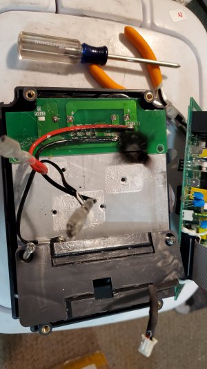
20200430_204938.jpg

This spot is opposite of where the burn is above. It looks like something popped here but with the 10X loop I couldn't really see any bad connections. Maybe a tiny bit of trace delamination but it still looked like it was connected.
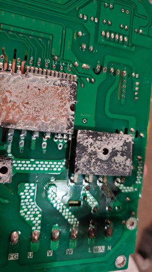

20200430_204953.jpg

I'm not entirely sure this was designed or assembled right. That solder spot o the board where it's close to the aluminum heat sink just doesn't seem right. Since I don't know if it was designed this way or not, I kept looking.
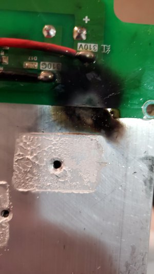

20200430_205243.jpg


Looking at the board below it's hard to see. The yellow relay is directly on top of where the soot blast was in the picture above. With a closer inspection I can see why I won't bother fixing it.
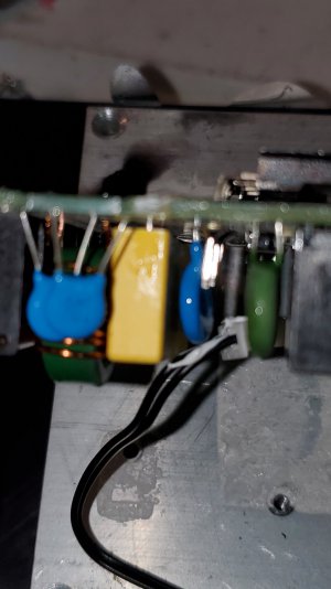
20200430_210040.jpg


It's difficult to see but there's definite trace delamination there. The trace blew like a fuse. I could solder jumpers to clear the bad trace but at this point I think I'll cut my losses and just buy another inverter. It kind of pisses me off because I think I may have gotten a faulty unit but I also know I hooked it up wrong.

20200430_210123.jpg

All in all, I'm not a happy camper about this.

Looking at the ground symbol in the plastic leads me to believe there's a ground in that area. There's the brake - symbol and the ground symbol. THe #6 lug supposedly a ground.
The screw by the plastic ground symbol wouldn't have grounded it. The #6 ground is what I had hooked up when the unit blew. And I blew my house circuit when I had the - on the brake hooked up.

Maybe the next one will go better.

I am concerned, however, that the 220v version says "line" and neutral also. 220v in the states doesn't have a neutral. How's that supposed to work?
 
Most VFD's are marked for 240VAC in the rest of the world which is N and L1 = 240VAC. In the US we have split phase so L1 and L2. VFD will instruct you as to the connections, typically for US use L1 is one phase and N is connected to the other phase (L2). Do not connect the neutral on a 240VAC VFD. You might consider a better VFD, but then people who buy these brands consider them disposable.
 
Back
Top