Weston DC Voltmeter Questions

G

Grumpy Gator

Forum Guest
Register Today
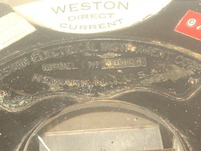
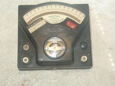
Anybody familiar with a Weston Model 1 No 48484.
I have searched the web but can't nail down the age of this unit.
I tried to check some batteries that I knew were good but could not get any readings.
Any ideas , suggestions or thoughts will be greatly accepted.
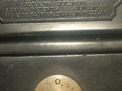
The last pattent date I could find was July 16 01. But I don't think they made Bakelite cases that long ago.
Pictures to follow:
*********G***********Weston Voltmtere 001.jpgWeston Voltmtere 006.jpgWeston Voltmtere 005.jpg


Weston Voltmtere 001.jpg Weston Voltmtere 006.jpg Weston Voltmtere 005.jpg
 
+ and 150 for 150 Volts DC
+ and 30 for 30 Volts DC
+ and 3 for 3 Volts DC
you place the (-) lead from the DC source on either of the 3 scales and the + on the common terminal - I think that it works backwards as the (-) is usually common in today's meters. You can see if this is the case by connecting the + side of a 1.5 volt battery to the common terminal and touch the wire connected to the (-) of the the battery to the 3 volt side - notice which way the meter swings - if it doesn't read from left to right (increasing scale) attempt to reverse the battery connection. Some of these old meters had a diode that prevented the meter from reading "backward". See if this helps!

Depending on the internal resistance of the meter, you may not have enough current flow to cause the meter to read - use a "D" battery of a 12 volt battery on the 30 scale and +.
 
They made that "model 1" pattern for many years, and you're right that a Bakelite case couldn't date to 1900 or even 1910. In the 1920 catalog the base is described as "polished mahogany" so presumably yours is later.
 
Nice meter, gator. I'm sure Alan has the old catalog. He's quite the collector. You might want to check the continuity of the coil to make sure someone hasn't damaged it. There will be shunting resistors for each range that are quite likely out of tolerance, or possibly even open. Given you saw no movement, that's a possibility also. Please resist putting voltage directly across the movement itself. It's a delicate mechanism and could be damaged. Good collector piece.
 
First Thanks All,
Pemedic: I tried with a 6 volt dry cell and a 12 volt car batt. No go.
Alan: I was guessing late 20s or 30s but had hopes the serial # would narrow it down.
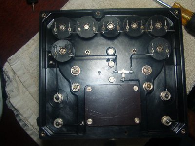
Tony:After reading your post I opened the back and took a look. I knew right off I was out of my depth. So I took a picture and closed it back up. I have to say that whoever put this together one damm fine mechanic.
****G****weston voltmeter 002.jpg


weston voltmeter 002.jpg
 
Weston made gorgeous equipment. They would scrap something rather than send it out in anything less than perfect condition. Of course the end user paid for that quality whether he wanted to or not.

The spools are wirewound resistors, and there should be one or more in series with each positive terminal. These sometimes open up, often from corrosion at the soldered terminal. If the moving coil itself is open, however, you're probably out of luck.
 
If you can still read the back of the actual meter inside it will say something like full deflection = 50 ma - ( a voltmeter is actually driven with current but uses a resistor as a shunt) with this information, you can figure out what resistance at the various voltages would cause full deflection and purchase wire wound 1% tolerance resistors to use as the shunts. This will make the meter useable again. Please also check that the wire between the terminals of the meter is not broken. I will attempt to type out what the wire(s) should look like:

3 Volt terminal -- [ shunt resistor ] ---\
\
15 volt terminal --[ shunt resistor ] ----O---------O---Meter ------------O---------- + terminal
/
30 volt terminal --[ shunt resistor ] --/

Hope this helps - you can use electrical formulas to figure out what the shunt resistor should be - probably it will be a really low resistance.
 
Your meter was made in 1933. I collected Weston's for many years and have cross referenced serial numbers with calibration dates, so I'm certain of the date. Having worked on (fooled around with) these for many years, I am not sure how much you can do. As suggested, you definitely need to make sure the movement itself is good before you go any farther! If that is open, it's game over. You have a paperweight. Using a modern ohmmeter you will need to check the resistance between the top hair spring coil and the bottom hairspring coil. I specify a modern ohmmeter because they use only VERY small amounts of current to get readings. If you use a battery, and the coil is good, you may perform a smoke test and vaporize the hairsprings! If you do get a reading of any amount, the movement has continuity so then you can look to check the resistance coils. Back in those days, the only way to get a specific resistance was to wind hundreds of feet of cotton covered manganin resistance wire on a spool. Ed Weston developed that technique back in the 1880's. As suggested, I'd resolder the wires. After so many years, many have corroded from the flux they used, but a touch of solder will bridge the micro-gap and you are in business. I would not try to fix one of those resistors! They have MANY feet of hair fine wire and if it has opened in one place, it may have opened in many others. Some of them have their resistance written on them in pencil, so look carefully for that clue.

If you want to take the cover off of the face of the meter, take off the two "nuts" that have slots cut in them with the screw projecting through the middle. Do NOT unscrew the two large screw s just above them! these hold the whole movement in place and you don't want to do that unless you plan some major surgery. You can check the resistors with an ohmmeter by putting it across the two connectors on the face of each of the resistors. Don't worry about the reading. In those old resistors, either they were right, or they were open (dead).

Good luck and hope this helps.

FGD
 
Back
Top