WF & John Barnes Drill Press

So nothing? Here"s a link to a guy who rebuilt a spindle on a similar but different drill press https://forum.canadianwoodworking.c...4446-small-drill-press-rebuild-leland-gifford

I'm a bit confused b my machine - in the linked article the guy mentions "pressing on the lower race" - and this is typical of more modern drill presses I have worked on (standard roller bearings) - bearings press on spindle and are housed inside the quill. In the case of this machine none of the bearing pieces press on - they are all slip fitting on the spindle.

Maybe its my lack of understanding regarding thrust bearings and thrust washers versus roller bearings? My proposed assembly above is just a guess. In operation the spindle is revolving inside the quill and the quill is stationary. Both upper and lower bearing surfaces (thrust washer and thrust bearing) and the quill are held together with the top threaded adjusting cap. As the spindle rotates the bearing surfaces would tend to rotate with it and the quill must be stationary. I initially I thought the softer bearing pieces (phenolic washer and brass race) should ride against the quill to prevent wear on the quill but I'm not sure that is right.

Second question - seems like sizing the loose balls would be based on them fitting in the machined race. In the linked article the two races don't come together - is that typical? my only experience with loose ball bearings was on a table rack mechanism on a, I think, Delta drill press and they were completely enclosed by the races.

I know there are quite a few folks who understand thrust bearings, spindles, etc that can offer suggestions - please feel free to educate me :)

Rick - who expects and will gladly accept "your nuts" comments
 
I was playing around with some different balls this morning. Seems like both 5/32/and 3/16 fit but the 5/32 seem to move in and out a lot - they don't fall out but the 3/16 seem more stable. While doing that I began questioning what the keyway in the spindle was for - I don't see any matching keyway in the frame casting at all.

Rick
 
Scratch the keyway question - I realized after posting it that the wheel that is driven off the friction disc is keyed to the spindle.

Rick
 
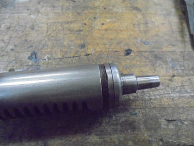
Here's the final (for now) spindle set up

Bottom

Final Spindle Set Up Bottom.JPG

Top

Final Spindle Set Up Top.JPG

I used 7/32 loose bearing balls - they seemed liken the best fit. I also placed the "softer " surfaces against the quill. Not sure if that is right or wrong - we'll see :)
I set the top cap to get smooth spindle movement and minimum end play.

Rick
 
Yes we did - late yesterday. I'm going to update later today


Rick
 
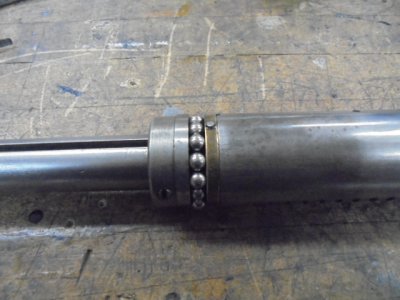
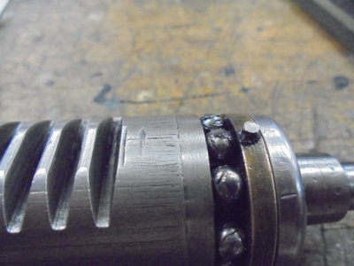
Based on a conversation with a guy on practical machinist (thanks Tom) The spindle arrangement shown above is not correct. The bearings need to go on the bottom of the spindle to absorb the thrust. I was concerned because of the pin in the brass race that was keeping the race from sliding over the spindle where there was not a keyway. I pushed the pin out of the ID and slid the race down.

Spindle Assembled Bearinng on Bottom Showing Pin in Race.JPG

My theory is that pin is acting as a stop for upward spindle travel. There is some disagreement on practical machinist - he feels like the pin may not be original and if I pulled it out completely everything would be fine - he is probably right but I'm going to leave as is for now.

I started a trial run of the final assembly (still need to do the painting) - there are some questions that I'll hold for the next post sometime today

Thanks
Rick
 
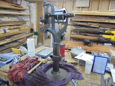
OK - I got everything together - let's start by saying everything below is conjecture so please feel free to enlighten me in one or all areas.

Overall Assy.JPG

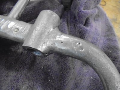
The first thing I noticed was that there appears to have been some damage/breakage to the upper arm for the spindle support on the main casting

Casting Damage Upper Spind;le.JPG

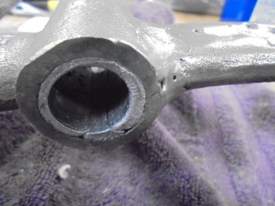
It appears to have been welded and, to my eye, it is a functional repair. In general the casting appears a bit rougher than the more modern casting I have dealt with. That could be due to previous owners use/abuse or just the level of technology in the 1890's. Several of the shaft holes appear to have a babbit like material or sleeve. Not sure if this is original bearing surfaces or another repair for wallowed out shaft holes.

Potential Babbit.JPG

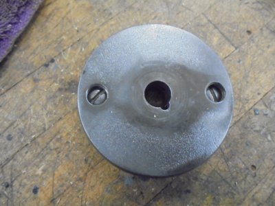
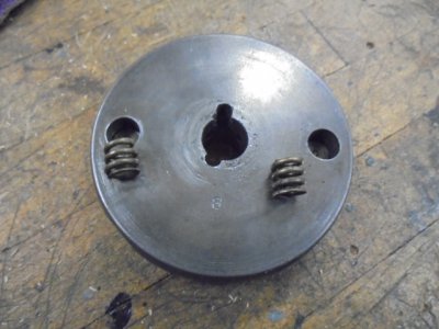
The first question deals with the quill tension adjuster. There is no quill return spring. There is simply a disc that has 4 radial holes for handles to lower the spindle to the work but the holes are not threaded. I'm not sure if the intent was to use handles that were press fit into the disc or simply slipped into the appropriate hole. However if the handle were too long it would interfere with the VS disc.

Also - the disc has two screws in the front and two springs on the rear - tightening the screws presses the springs into the a machined casting surface that sets the tension on the quill - at least that's my theory. I'm assuming they should be tight enough to keep the quill from dropping on its own but loose enough to provide smooth operation.

Quill Tension Adj Screws.JPG

Quill Tension Plate.JPG

Quill Tension Springs.JPG

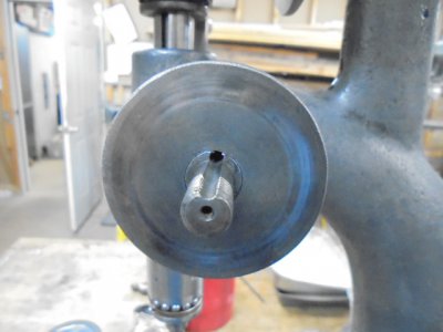
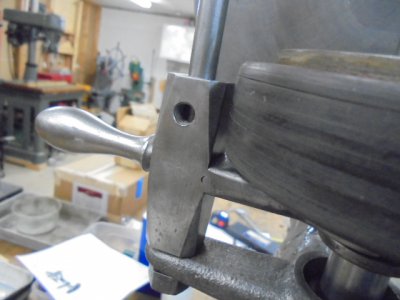
The next area of concern is the VS wheel that [presses against the VS disc. This has a lifting fork that was on top of the wheel when I got the machine. That resulted in the wheel not reaching the top of the VC driving disc. When I looked at the catalog page for this machine it shows the wheel with the lifter underneath so I changed mine. Not sure why mine was reversed but un less someone has a good reason I'm going to leave it as the catalog shows. On the same parts - there is a threaded hole on the lifter that is a through hole. I'm assuming it is for locking the VS wheel in the desired position. Mine didn't have any locking screw so I'm wondering if anyone has an idea what that locking fastener might look like? Left to my own devices I would probably use a thumb screw but would like to get close to original if possible. I'm also assuming it is a through hole so that the option is there to lock it from either side (or maybe both sides)

VS Wheel Lifter.JPG

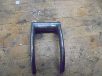
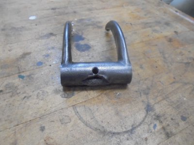
Finally is the belt transfer fork. This is used to transfer the belt from the fixed driven pulley to the idler pulley. Mine is missing the locking fastener and appears to have a handle that was broken off. That might be a candidate for brazing/welding if I can find/fabricate an appropriate handle so if anybody knows what that looks like please let me know. It would be great if I could find one but I doubt that will happen. When I got the machine the fork was on upside down and I put it back that way for now. The catalog page shows it with the forks facing up - I'm assuming the design was for an overhead flat belt drive but with a motor drive underneath it had to be reversed. The whole drive method with a motor has questions around it - this machine does not seem to lend itself to good placement of the motor to drive the pulleys from underneath but mor to come on that later.

Broken Belt Transfer.JPG

I can get additional pictures of any or all areas if that would help clarify

Rick
 
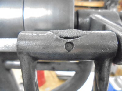
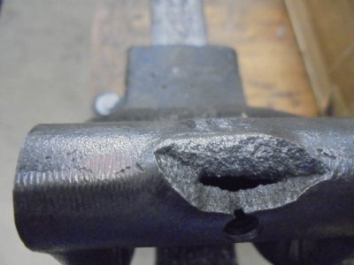
I decided to focus on one problem area at a time - today it is the belt transfer lever. That lever bas a break just above where the handle would be and the handle is missing

The lever overall

Belt Transfer Lever.JPG

The break

Broken Belt Transfer Lever 2.JPG

Close up of the break

Broken Belt Transfer Lever.JPG

You can see the drilled and tapped hole for the handle that you would grab to slide the handle over. I'm thinking possible fixes for the break would be welding, brazing, JB Weld, others? Any suggestions? I tend to view this as more aesthetic than functional but maybe not? If its just looks then maybe JB Weld is an acceptable solution/ I don't weld or braze so JB Weld would be easiest for me.

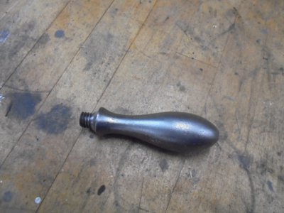
I'm not sure what the handle itself looked like but I'm thinking something like this would work

Domed Handle.JPG

This is actually off another area of the machine so it fits with the machine design. I know I can get one at McMaster but I'm going to try a WTB postimg first

I'm open to any other handle suggestions. Note that the handle needs to lock the lever to its shaft - not sure that is how the original worked but I think that is the best solution now.

Rick
 
Our computer does not have a functional scanner, but I could copy it and send by USPS, PM me with your contact info.
John
John - got the catalog page - thanks! They are certainly different machines. Your catalog is 1897 - mine appears in the 1898 catalog

Rick
 
Back
Top