What Chuck On Rotary Table?

ChipsAlloy!

Active User
Registered
Joined
Jul 10, 2013
Messages
102
I am thinking of buying a rotary table for a project I am planning in the next couple months. I was wondering what kind of chuck to get with it? I would guess a plain back chuck with some adapter plate to attach to the RT. Also is there any advantage to having a 4 jaw chuck mounted on the RT? I would think you can make an offset using the mill table so why would one use a 4 jaw instead of 3? Im sure im missing something important here, but the question just popped and its late so ill just throw it in anyway. ;)
 
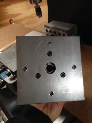
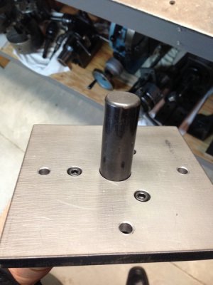
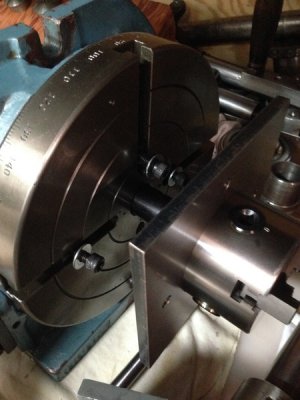
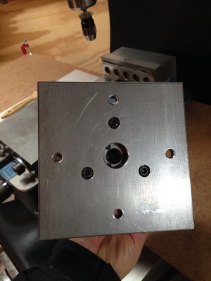
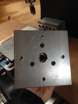
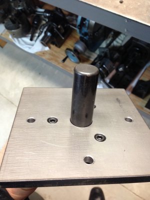
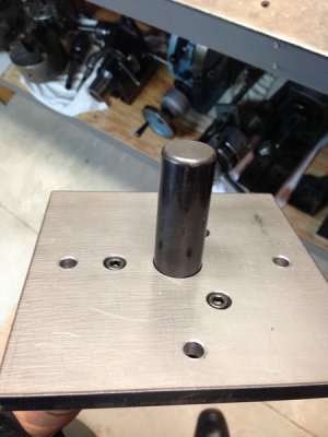
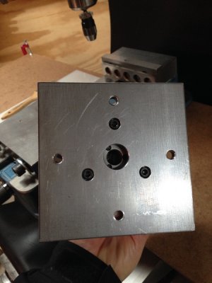
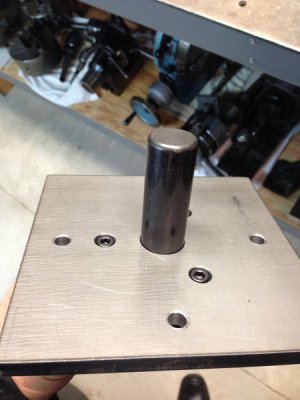
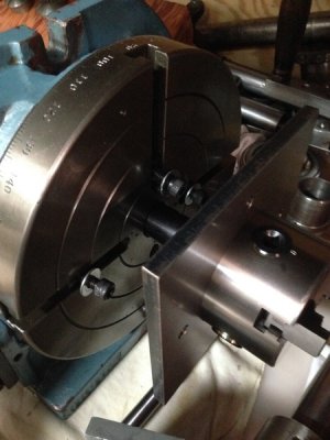
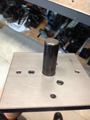
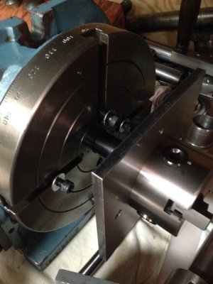
I made a fixture plate for my vertex 8" RT that I can bolt a 3-4 jaw Chuck to , they all center on a 3/8 dowell pin in the RT mt3 center. The plate also has other threaded holes for clamping . Might check this thread out.
New Rotary Table And Chuck
Discussion in 'MACHINE ACCESSORIES' started by 3dshooter80, Jan 12, 2016.
 
I have a 6" RT with both a 4 jaw and 3 jaw self-centering. I used the 3 jaw once and never again. I can dial the 4 jaw in with a dial indicator and KNOW it's on center. The three jaw is always a little off. Even after regrinding the jaws, it's better but not good enough.
 
The three jaw will not center your work accurately to the center of the RT unless you indicate the work to the table center and hold the chuck down to the RT with toe clamps or similar. The RT needs to be centered under the spindle before starting any work. Everything proceeds from there. If you offset the mill table to the center of the work in the inaccurate chuck, it will only be accurate in that one clock position. As soon as you index the RT you will have errors.

A rotary table, as purchased, is not really very useful. Using the T-slots and toe clamps and indicating the work is really slow and tedious, but sometimes necessary for odd shaped work or offset work. Look at dlane's very nice pallet build (above} for ideas on how to mount fussy work.

A lot of the work we do on the RT is symmetrically radial, like typical lathe work. What you really want to do is to chuck it up and start cutting. A three jaw chuck makes that very easy, but it has its own issues. First, the chuck has to be centered on the RT, and that takes time and effort. Second, three jaw chucks, by their construction, are not inherently accurate. Four jaw chucks are versatile, and are as accurate as you want to make them, by dialing the work in. But they are slower, especially if you also have to cobble together hold downs for the chuck to the RT as well. The shape and size of the work also matters. You are not going to put square stock in a 3 jaw chuck. You are not going to mount 12x12" work to a 8" RT by the edges, or fit it in a chuck.

Most rotary tables have a Morse taper center hole. With a bit of one time effort, we can build a centering fixture to center the RT and also to adapt chucks to the fixture. There is a very good set of videos by Randy Richard on how to do this:
There are six parts, this is part one...

I have chucks from my indexing head tooling that are 1-3/4", 8 TPI and are direct mounting, no back plates. They are small, 6" four jaw and 5" three jaw. If the Morse taper adapter for the table is made with an accurate thread, say 3/4-16, that stands above the table, and then an adapter is made from the 3/4-16 to the 1-3/4-8 chuck thread then the chuck adapter screws to the RT adapter which mounts to the RT, and the chuck can screw down tight directly to the RT surface. The faces of my chucks are less than 2" off the table. That is important. Headroom is compromised by rotary tables, adapters, chuck, work, and tooling. It is very easy to run out of headroom, even on a larger knee mill. You do not want a bunch of tall stuff stacked up...

Try for maximum adaptability and versatility in the fixtures you make for your RT. Also, try to achieve maximum speed and ease for changing setups using indicating and clamping aids. You will likely need to make all this yourself, but it will be a great learning experience and will be well worth the effort.
 
Great thanks a lotfor all the info. I will check the videos after work.
 
All good comments. I never really cared for setups that went Rotary table MT socket > male MT adapter > plate adapter > chuck recess or threaded mount. Too many nested positions of collective run-out. Then add typical 3 -jaw run-out on top of that. My method is to pre-attach a plain back chuck to a self made plate, typically using the chuck's back screws or through bolts depending on the chuck. The RT has been pre-centered to mill. The plate has a center hole in it. Picture as a giant accurate washer. It also has slots or holes matched to your RT. With the chuck/plate assembly loosely tightened to RT in ~center position, I dropped in an accurate ground MT socket arbor into the RT. It had sufficient stick-up so that the 3 jaw chuck could be lightly gripped on the plain diameter cylindrical portion. Now secure the plate to RT t-slots, unscrew the 3-jaw & remove arbor. Its about as close to pre-zeroed as you can get for this level accuracy & is pretty fast setup. I could repeat 0.0005" - 0.001" with a ground test bar. I think the jaw pre-loading helps a bit too (but probably confined to that approximate arbor slug diameter). Now I just cant recall where I got that particular MT arbor, but they are available or one could be made to suit.

Of course, a 4-jaw gives you absolute control
 
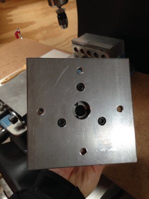
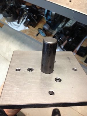
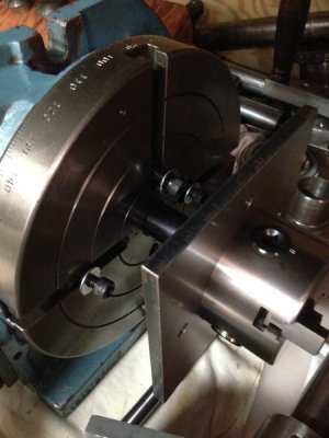
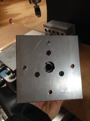
My Troyke 9" is a nice 1.000 dia straight hole in the center. A 1" dowel pin slides in semi snug. I machined the 3/8" thick adapter plate with a 1" center hole to match in same setup that i machined a recessed pocket to bolt chuck into. Pretty much bolt it to the t slots with dowel in, once bolts tight tap out dowel (if req) and she is dead nuts with RT rotation.
A tapered hole would be a pita.
7293c521667b43fbfebd960da3a7b9e9.jpg
e217bab737d86eaff2ede0c8e1c497eb.jpg
b10e314b5039b7c9efc0bc84f4cba6a5.jpg
This is my little 3" 3-jaw. Have a similar plate for my 6" 3&4 jaw chucks.

7293c521667b43fbfebd960da3a7b9e9.jpg

7293c521667b43fbfebd960da3a7b9e9.jpg

7293c521667b43fbfebd960da3a7b9e9.jpg

e217bab737d86eaff2ede0c8e1c497eb.jpg

e217bab737d86eaff2ede0c8e1c497eb.jpg

e217bab737d86eaff2ede0c8e1c497eb.jpg

b10e314b5039b7c9efc0bc84f4cba6a5.jpg

b10e314b5039b7c9efc0bc84f4cba6a5.jpg

b10e314b5039b7c9efc0bc84f4cba6a5.jpg

7293c521667b43fbfebd960da3a7b9e9.jpg

e217bab737d86eaff2ede0c8e1c497eb.jpg

b10e314b5039b7c9efc0bc84f4cba6a5.jpg

7293c521667b43fbfebd960da3a7b9e9.jpg

e217bab737d86eaff2ede0c8e1c497eb.jpg

b10e314b5039b7c9efc0bc84f4cba6a5.jpg
 
Nice, thanks a lot for sharing I am starting to get a general idea of what can be done to mount the chuck. I am still hesitating between a 6" and 8" table.

My mill is a PM932. I only have 18 inches max from mill table to spindle. The 8" fits on the table but Add to that a drill chuck or whatever tool plus the actual part. i dont know... Any input on that from some 932 or similar users?:confused:

Ill go and watch the videos Bob Korves talked about, I have watched the first one and it is quite interesting.
 
Back
Top