- Joined
- Feb 24, 2019
- Messages
- 925
I have a mid sized mill/lathe combo.
I added a DRO.
My biggest complaint, now, is having to switch gears every time I want to change the crossfeed screw and that the X-axis feed works at a much faster rate than the Y-axis. So to get the Y-axis to feed at the same rate, I'd have to swap gears. No fun.
I also am not excited about the junk transmission the crossfeed has. To pop out of position (for/rev) takes significant effort but to bypass the neutral indent is super easy so it can go from left to right accidentally. I also don't like that I have to run the lathe in order to have an automatic feed when I'm milling.
Nuff said about what I don't like.
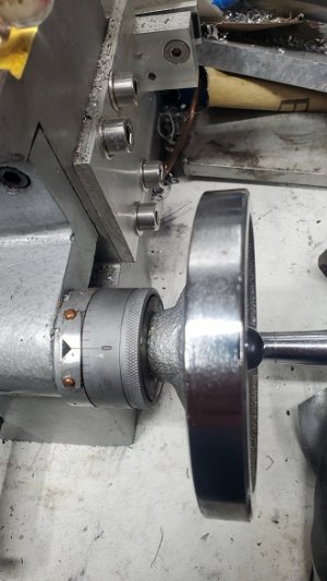
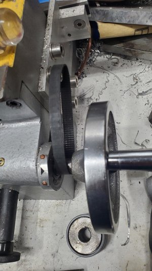
On the right end of the crossfeed screw is a handwheel that's supposed to be for setting position. With the DRO I haven't used the indicator even once.
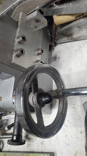
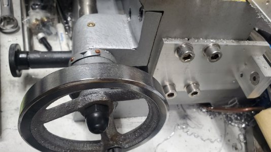
It hangs far enough off the end of the machine that there's room to put a gear there.
I have a plate I added to that end to support the right end of the DRO rail.
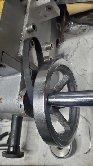
I'm thinking of removing the indicator wheel and replacing with a timing gear. Then attaching a stepper to the plate for the DRO and running a belt to the crossfeed screw.
I can add the feed wheel back on in case I ever need it but the crossfeed would be powered by the stepper, unless I'm threading. It would be able to have speed control and reversible. Only downside that I can see is that if I use the feed wheel it will put "work" into the stepper which would feed power back into the controller. I don't know that this is an issue though.
What do you think?
(Belt placed just to show perspective)


