What is acceptable error for threads? MT2-M39x4 chuck adaptor for rotary table

durableoreo

H-M Supporter - Gold Member
H-M Supporter Gold Member
Joined
May 3, 2020
Messages
229
When cutting threads, how much error can be tolerated? I'm thinking in terms of % error on TPI, comparing calculated value to nominal.

I need to cut an M39x4 thread, which is not on the chart for my lathe (Harbor Freight 9x20). I counted some teeth, looked inside the 9-position gearbox, and eventually made a spreadsheet. Simple, right? Well, the TPI numbers did not match the documentation on the lathe. So I chased my tail for a while. After trying and text books had failed, I decided to look at a calculator. Turns out, I was right all along and there's just a lot of error. http://www.spokecalculator.net/other/cgc/

The whole point of this exercise is to be able to move the chuck between the lathe and mill without taking the part out. I've already cut flats on the chuck's backplate, which is convenient for mounting the chuck in the mill's vise. It adds up in Z distance but so far, so good. Now I'd like to extend that flexibility to the rotary table.

While you're here, do you think an MT2-M39x4 adapter will work for holding a 6-jaw chuck onto a rotary table? It's the 6" Grizzly H7527. If it's set up in the normal way, rational axis parallel to Z, I think it would be OK. Set up on its side, I'm less sure about. Normally the M39x4 has a thread, land, and shoulder. The thread secures the chuck against the shoulder and the land provides concentricity. If the rotary table surface IS THE SHOULDER, could it be rigid enough for light milling?
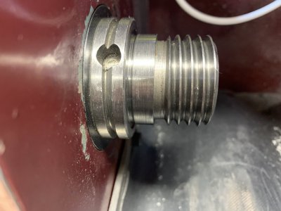
m39x4_spindle.jpeg
 
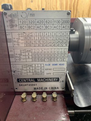
Things aren't making sense so I eventually suspected the plate. I noticed the gear drawings were identical in all 3 cases (imperial threads, metric threads, and feed). Also, the change gears include pair of 80-tooth gears, which I had never used. Eventually I realized the 127/120 compound is probably for metric threads only, and the 80/80 compound is for imperial threads.

lathe_plate.jpg


A while back I was cutting threads and it seemed to be taking a lot of passes---too many, according to your collective experience. This error in gearing may have contributed to that problem. Cutting deeper threads results in a sloppier fit if the helix in the nut and stud match. But in my case, the helix on the stud was off by 6%, so the slop was needed. In that particular case the nut was fairly long, 1.5 diameters, which would have made the problem more obvious than a typical hardware-store nut, which is loose and engages less than a diameter.

So the answer to the original question is 6% error on TPI is too much.
 
With 100 to 127 transposition gears your metric threads should be near perfect, so yes 6% is way too much.
You must have something else going on to have that much error
 
About the last part of your question: Not sure how you are securing the adapter to the rotary table, but if it's just a friction fit of the MT2 holding a 6 inch chuck, it's going to move. I made a similar adapter on a 6 inch table for a 4 inch chuck, and it would rotate. I needed to make stop screws in the table's slots to restrain the chuck.
 
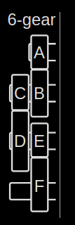
With the change gears I have, there are too many combinations. Lots of them are impossible. I had to make my own calculator to make sure the combinations are reasonable. For example, Gear A can't be bigger than 80 teeth because the stud of an idler will interfere with it. A and B most be big enough that they can reach due to the length of the slot on the banjo. The radius of C + radius of D must be bigger than the radius of B. And so on. The code is below. It's a draft so don't bet your life on its output.

Originally I wanted to cut 4 TPI threads. From the program, this solution works in theory and on the lathe itself: A=80, B=80, C=120, D=30, E=16 (in gearbox), F=16


6gear_scheme.png

#!/usr/bin/perl -w

use strict;

## Find reasonable 6-gear combinations for a particular TPI. This calculator
## knows the difference between change gears and transmission gears. There are
## limits---for example, I can't mount a huge gear on A. The total length of
## the gear train must be long enough to span the stud for A to the stud for D,
## etc.


my $argc= $#ARGV + 1;
if( $argc != 2 ) {
print( "USAGE: change_gears.pl <TPI> <starting %error> \n" );
exit( 1 );
}

#requested TPI
my $TPI = $ARGV[0];

my $TPI_ERROR = $ARGV[1];

my @TRANS = (16,18,19,20,22,23,24,26,28); # import 9x20 from Harbor Freight w/9-position gearbox
my $TRANS_FIXED = 16;

my $LEADSCREW = 16;

my @CHANGE = ( 28, 30, 30, 36, 42, 45, 60, 80, 80, 120, 127 );
my @RAD = ( 1.180/2, 1.261/2, 1.261/2, 1.500/2, 1.735/2, 1.850/2, 2.436/2, 3.225/2, 3.225/2, 4.793/2, 5.068/2 );


print( "\n" );
print( " Gearing for $TPI TPI\n" );
print( "\n" );
print( " A B C D E F Lead TPI Error\n" );
print( "-------------------------------------------------\n" );

my $count = 0;
my %seen;
for( my $i = 0; $i <= 8; $i += 1 ) {
for( my $a = 0; $a <= $#CHANGE; $a += 1 ) {
for( my $b = 0; $b <= $#CHANGE; $b += 1 ) {
for( my $c = 0; $c <= $#CHANGE; $c += 1 ) {
for( my $d = 0; $d <= $#CHANGE; $d += 1 ) {
for( my $f = 0; $f <= $#TRANS; $f += 1 ) {

my $TA = $CHANGE[$a]; # tooth count of Gear A
my $TB = $CHANGE[$b];
my $TC = $CHANGE[$c];
my $TD = $CHANGE[$d];
my $TF = $TRANS[$f];

# Make sure we're not using a gear more than once
if( $a == $b || $a == $c || $a == $d ) { next; }
if( $b == $c || $b == $d ) { next; }
if( $c == $d ) { next; }
if( $TA > 80 ) { next; }
if( $TA + $TB > 200 ) { next; }

my $RA = $RAD[$a];
my $RB = $RAD[$b];
my $RC = $RAD[$c];
my $RD = $RAD[$d];

if( $RA + $RB < 2.25 ) { next; }
if( $RC + $RD < 0.9*$RB ) { next; }
if( $RA + $RB + $RC + $RD < 6.2 ) { next; }

my $ratio = $TA/$TB * $TC/$TD * $TRANS_FIXED/$TF;
my $lead = $ratio/$LEADSCREW;
my $tpi = 1/$lead;

my $error = abs($tpi-$TPI) / $TPI * 100;
if( $error < $TPI_ERROR ) {
my $str = sprintf( "%3i %3i %3i %3i 16 %3i %4.3f %5.2f %3.2f\n",
$TA, $TB, $TC, $TD, $TF, $lead, $tpi, $error );

if( ! defined $seen{$str} ) {
print( $str );
$count += 1;
$seen{ $str } = 1;
}
}
}
}
}
}
}

if( $count >= 10 ) { last; }
$TPI_ERROR *= 2;
}

print( "\n\n" );
 

Attachments

  • all.pdf
    108.2 KB · Views: 0
About the last part of your question: Not sure how you are securing the adapter to the rotary table, but if it's just a friction fit of the MT2 holding a 6 inch chuck, it's going to move. I made a similar adapter on a 6 inch table for a 4 inch chuck, and it would rotate. I needed to make stop screws in the table's slots to restrain the chuck.

Thanks. I'll take that into consideration. I'll plan on some clamps.
 
Your M39x4 is not tpi, it is a 4mm pitch. When you calculated the threads not being correct, are you doing it with the 120/127 gear set up properly? The difference is 5.8%.
 
Your M39x4 is not tpi, it is a 4mm pitch. When you calculated the threads not being correct, are you doing it with the 120/127 gear set up properly? The difference is 5.8%.

Oh, I pitch and TPI confused. Missing the forest for the trees. Now that I'm looking int the right place, the thread chart only goes to 3 mm. Luckily I already figured out the formulas...

4 mm = 0.15748 in --> 1 / 0.15748 = 6.350 TPI


Gearing for 6.35 TPI

A B C D E F Lead TPI Error
-------------------------------------------------
80 127 120 30 16 16 0.157 6.35 0.00
80 45 127 60 16 24 0.157 6.38 0.44
80 45 127 80 16 18 0.157 6.38 0.44
80 60 127 45 16 24 0.157 6.38 0.44
80 80 127 45 16 18 0.157 6.38 0.44
80 120 127 30 16 18 0.157 6.38 0.44
80 42 120 80 16 18 0.159 6.30 0.79
80 42 127 80 16 19 0.159 6.28 1.05
80 80 120 42 16 18 0.159 6.30 0.79
80 80 127 42 16 19 0.159 6.28 1.05
80 120 127 28 16 19 0.159 6.28 1.05


Pretty sure that first row would work

RE the 5.8% error. I got a lot of that when I was calculating imperial threads with the 127-120 compound gear.
 
Added all the metric pitches from 0.13 to 6.75, at the end. Not all are standard but all the standard pitches should be in there.
 

Attachments

  • all.pdf
    147.5 KB · Views: 1
Back
Top