Where do I go from here ?

ltlvt

H-M Supporter - Sustaining Member
H-M Platinum Supporter
Joined
Aug 29, 2019
Messages
525
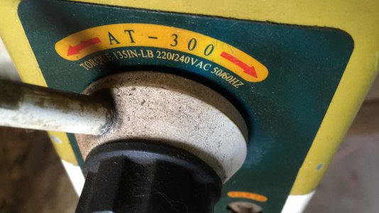
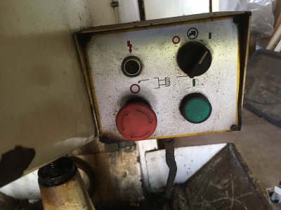
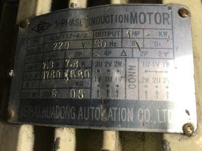
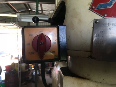
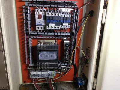
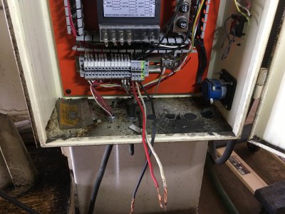
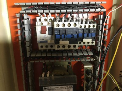
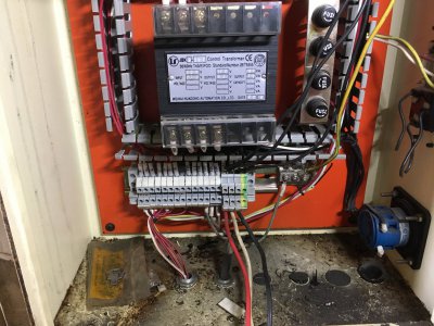
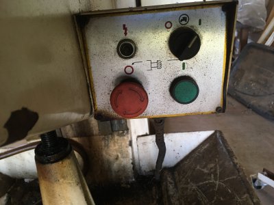
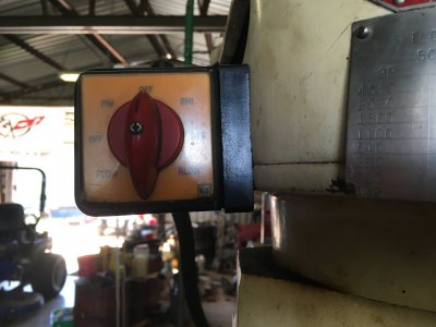
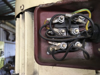
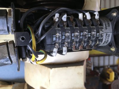
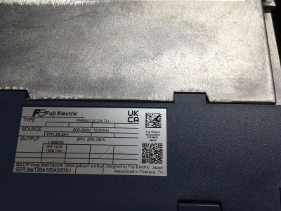
The pictures I am posting are the electrical panel and some of the controls on my New to Me 3 hp McLane mill. It seems to be the same as a Jet or any of the other BP clones. It does have the 54" table. My question is can I just run the output leads from my Fugi VFD to the power leads at the bottom of the panel (red-white-black) or am I going to hook the VFD directly to the motor leads? I would like to keep the rotary switch that is on the front of the mill rather than starting it from the run key on the VFD. The pictures may be more than someone needs to see but I am trying to give a good representation of what is on the mill. Thanks in advance.
 

Attachments

  • IMG_1001.JPG
    IMG_1001.JPG
    438.7 KB · Views: 23
  • IMG_1002.JPG
    IMG_1002.JPG
    473.9 KB · Views: 25
  • IMG_1006.JPG
    IMG_1006.JPG
    475.5 KB · Views: 21
  • IMG_1004.JPG
    IMG_1004.JPG
    520.9 KB · Views: 22
  • IMG_1028.JPG
    IMG_1028.JPG
    513.7 KB · Views: 19
  • IMG_1031.JPG
    IMG_1031.JPG
    452.9 KB · Views: 22
  • IMG_1035.JPG
    IMG_1035.JPG
    307 KB · Views: 21
  • IMG_1039.JPG
    IMG_1039.JPG
    426.6 KB · Views: 22
  • IMG_1047.JPG
    IMG_1047.JPG
    376.7 KB · Views: 19
  • IMG_1054.JPG
    IMG_1054.JPG
    711.7 KB · Views: 26
You'll need to connect the VFD output directly to the motor (and only one motor).

If anything else on the mill run on 3 phase, you'll need to provide a separate power source for it.

I'm confident that someone (many) here can help guide you regarding how to reconnect your existing switches to tell the VFD what to do.
On/Off, Fwd/Rev, E Stop (you'll want to add speed pot too).
They will probably need to know the Mfg/Model of your VFD.
 
Yes what extropic said is correct, you must wire a VFD directly to only one motor, with nothing else in the circuit. You can wire the Mill's switch to the VFD's control inputs, so the switch will function normally. Though you might need a relay or two to complete the interface, it depends on the VFD you have ? Here is a link to how I wired my mill to the VFD:

If you want "Plug & Play" using the mill as is, you will need a Rotary Phase Converter.
 
...The pictures may be more than someone needs to see but I am trying to give a good representation of what is on the mill.
For my own curiosity, I'd like to see a picture of the mill that requires all that complex circuitry. What more than the mill power is controlled?
Aaron
 
Looks like a fairly typical 3 phase motor setup, although the RLO/RHI switch makes me wonder if it could be a 2-speed motor. The cabinet looks pretty typical: An overload, a couple of contactors, one for forward, one reverse, a transformer to handle lower voltage control. To wire in a VFD you will basically strip almost everything out of that cabinet and replace it with a VFD. If it is a 2-speed motor, you'll wire the VFD to one of the speed options only and not use the other.

As @AGCB97 mentions, more pictures would be good. Motor data plate in particular.
 
Last edited:
If you want "Plug & Play" using the mill as is, you will need a Rotary Phase Converter.
Please folks, don't forget the static phase converter option. Inexpensive, quiet, trivial to hook up, and the idea that you are getting less power is substantially exaggerated.
 
For my own curiosity, I'd like to see a picture of the mill that requires all that complex circuitry. What more than the mill power is controlled?
Aaron
It is badged as a McLane but the research I have done is that it is a generic Bridgeport Clone Marketed as Jet, Birmingham, Precision Mathews MSC and any others you might be able to name. I will see how accurate it is once I get it running which should be soon. It has Turcite on the female ways so that makes it rebuildable if need be, without all the added expense. Just looking at the table it has not been used by idiots, but time will tell when I try to hit the numbers. I just finished programing the Fugi Mini-Series VFD for it and tested it out on a bench motor I have and also a 3-position toggle switch to simulate the rotary switch for Fwd. and Rev. All is looking good so far. I am pretty sure it is a 2-speed motor but my plan is to only use one speed. How I do that is yet a mystery to me. LOL I am a 71 year old student of Lectricity.
 

Attachments

  • IMG_1028.JPG
    IMG_1028.JPG
    513.7 KB · Views: 5
  • IMG_1030.JPG
    IMG_1030.JPG
    471.3 KB · Views: 13
  • IMG_0966.JPG
    IMG_0966.JPG
    423.6 KB · Views: 13
  • IMG_1032.JPG
    IMG_1032.JPG
    304.2 KB · Views: 13
I did my own VFD. I ran the VFD directly to the motor and used the VFD remote (on off) to the original motor starter relay start stop switch.
 
Looks like a fairly typical 3 phase motor setup, although the RLO/RHI switch makes me wonder if it could be a 2-speed motor. The cabinet looks pretty typical: An overload, a couple of contactors, one for forward, one reverse, a transformer to handle lower voltage control. To wire in a VFD you will basically strip almost everything out of that cabinet and replace it with a VFD. If it is a 2-speed motor, you'll wire the VFD to one of the speed options only and not use the other.

As @AGCB97 mentions, more pictures would be good. Motor data plate in particular.
Should I use high speed or low speed?
 
It's ok to leave the switch inline to have it selectable, so long as you're disciplined enough not to use it while running. You need to use the VFD controls to start and stop. This is probably the simplest way to hook it up as you only need to join the VFD into the switch input, not deal with the mess the other side. Select a speed, then pull the nob off the switch is another way to look at it.
 
Back
Top