Where do I go from here ?

Should I use high speed or low speed?
Looking at the motor plate, it draws roughly the same current either hi or lo. That suggests it is about the same HP either way. Twice the torque at 1/2 the speed. Others with better y/delta motor knowledge may weigh in.

Because of the way VFDs work with motors I would use the low speed (4 pole delta, left side connection diagram on the motor data plate) and then allow maybe 30Hz to 150Hz at the VFD. That would give you 1/2 the original spindle RPM at the low end to 2.5 times the original lo rpm at the hi end. These settings are not an exact science, you should be aware of the motor temp for a while until your really comfortable with the setup, especially at the low rpm end of the range when working it hard.

Be sure to folow the VFD setup process, get the data plate figures, particularly amps, entered into the vfd, and let the vfd run its tuning process.
 
I did what Lo-Fi suggested and fed the VFD to the two speed selector switch on my drill press. As with yours, both windings draw about the same current. May as well utilize the benefits of the two speed motor.
As said, don't switch while under power.

Greg
 
I did what Lo-Fi suggested and fed the VFD to the two speed selector switch on my drill press. As with yours, both windings draw about the same current. May as well utilize the benefits of the two speed motor.
As said, don't switch while under power.

Greg
Since you're switching between a 2 pole and four pole setup, that is basically running two different motors with the same VFD settings. The VFDs do some optimization for motor parameters beyond just current, so I don't think that's best-practice in all situations. But, WTF, if it works ...
 
I'm by no means an electrical guru, but wonder if the entry for number of poles simply corrects the rpm meter on the VFD. The tech I spoke with at Automation Direct said there'd be no problem running the two speed motor, with the caution of not switching it while running.

Greg
 
Yes what extropic said is correct, you must wire a VFD directly to only one motor, with nothing else in the circuit. You can wire the Mill's switch to the VFD's control inputs, so the switch will function normally. Though you might need a relay or two to complete the interface, it depends on the VFD you have ? Here is a link to how I wired my mill to the VFD:

If you want "Plug & Play" using the mill as is, you will need a Rotary Phase Converter.
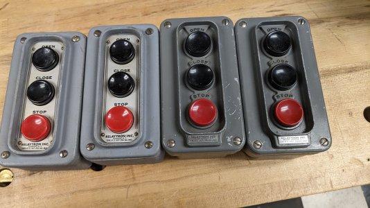
That's nice. I have a bunch of those switches. I would like to take them and add a potentiometer for my switch to the top to control it.
Thanks for the info. All I need to do is replace the label for open and close to FWD, REV.
PXL_20230317_185808585.jpg
 
Since you're switching between a 2 pole and four pole setup, that is basically running two different motors with the same VFD settings. The VFDs do some optimization for motor parameters beyond just current, so I don't think that's best-practice in all situations. But, WTF, if it works ...
It's not really like two motors... Yes, you're switching between series and parallel connection of winding pairs, but you can't, for example, stall one of the sets of windings as you would be able to driving two motors. The armature is common and they have matching characteristics regardless of how they're arranged, so I doubt it'll give a VFD much trouble.

The scheme used on those two speed motors is called Dahlander, if anyone if interested.
 
It's not really like two motors... Yes, you're switching between series and parallel connection of winding pairs, but you can't, for example,
Sorry, the academic in me is coming out, although I'll admit motors wasn't my specialty area.

The Park transformation is used to estimate/linearize the flux parameters in a sensorless vector control motor. This is what "tuning" a VFD does, the VFD attempts to measure several magnetic flux related parameters by analyzing the motor behavior, ideally totally unloaded. Given how the Dahlander motor changes the configuration of the windings, including some of the potential non-linearities associated with saturating magnetic fields and such, especially when operating at different RPMs, I'd want to see a further analysis to believe that is definitive. Not saying it isn't true but I don't think it immediately follows.

edited to add: I no longer have full access to IEEE Explorer as I did, but a review of some of the research papers I could find in this area leads me to believe there are definitely questions associated with this. Now, this all comes down to how well your speed control algorithm works, in other words how close to maintaining the same RPM as the load changes. So how good is good enough? If you switch motor configurations and the RPM control isn't a problem coming and going into a cut, then you're good. I'm guessing a mill would be more forgiving than a lathe. I'd be curious if @mksj has some experience/thoughts here. Of course you could set up the VFD in V/f mode to bypass the question totally.
 
Last edited:
My Automation Direct VFD has multiple motor parameters, and I use a spare contact on the Low/High switch to a VFD input so the VFD switches motor parameters when the L/H switch is changed. Seems to work well, though I rarely use the high speed. I let the VFD auto tune each configuration.
 
If it is a constant hp motor, then there is no reason to setup the VFD for both windings. Connect it as a 4 pole winding and run the motor 30 to 120hz. Depending on the VFD, the motor parameters are for the specific winding configuration especially when motor tuning. Winding resistance values change depending on the winding connections. VFDs with 2 motor settings I have configured for 2 speed motors and not found it to be of any benefit.
 
Back
Top