Who owns a Grizzly 4003 lathe from 1999 to 2005 ?

Before you do anything I would test this, Nothing else on your lathe has matched the current diagrams so I would definitely test

You would have to find the U1, U2, Z1, Z2 wires going to the motor,
You would have to run wires appropriate to the load to your new drum switch
You would have to run power L, N and G to your new drum switch

I dont know your new drum switch so you would have to figure out the new switch using an ohm meter to get the appropriate combinations I mentioned above.


The wiring diagram the fella posted earlier has to be for my lathe. No wires have been altered in location. I'm the only one that has ever had access to the lathe.

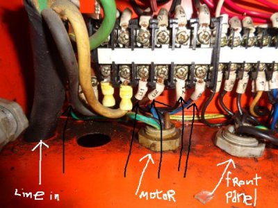
In the picture above, the left gray plastic nut/ferrule with the wires coming thru it and going to the power strip are the only wires leading to the motor.

they are labeled
PE = green/yellow (ground)
U1 = black
U2 = brown
Z1 = black
Z2 = blue

They come from the service access box on the motor, in it's own plastic tube, thru the left gray plastic ferrule and terminate here on this power strip

the 5 wires thru the center gray plastic ferrule is a single harness that goes straight to the estop/powerstart/jog/light user panel on front of lathe

the 5 wires from the right side gray plastic ferrule is the harness straight to the drum switch,

All of these harnesses go straight to their end items, no harnesses split and go off to anything else.
(you can unhook the 5 wires from the drum, then pull the entire harness right out the back of the lathe, same with the other 2 harnesses, just unhook them at one end and pull it thru. So I can "de-wire" all 3 components and have 3 separate 5 wire harnesses laying on the floor in less than 3 minutes.

So knowing that

the line in (220v) is the large black lead coming thru the far left bottom of box (large white/black/green wires)

the left gray ferrule are all 5 motor wires,

the center gray ferrule has 5 wires (+ ground) leading to the front user panel,

the right gray ferrule has all 5 wires to the drum switch

how do I proceed to eliminate the user panel and it's harness from the lathe and hook the motor direct to the drum switch?
DSC02906.JPG

Thanks,
Mutt
 
My G4003 was purchased July 1998. The date on the Grizzly inspection report is hard to read but looks like 1991 (probibly '97). The 4003 is no marvel of fine workmanship but it has done all I asked of it and I have learned to wook to a couple of tenths when that level of tolerance is needed. I have had no electrical issues so I can't give any advice on the reversing switch.
Hope this diagram helps. Looks like there is already a lot of good feedback.


Does your diagram tell which cap is teh start and which is teh run? There is one on the top, and one on teh bottom of the motor when the motor is mounted.
 
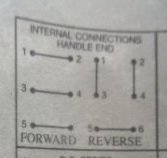
Not sure how I can help you anymore then I have with your new drum switch, You would have to find a manual for the drum switch or use a ohm meter to figure out how to make the pattern I listed above (the old sketch and new manuals all show this pattern):

There are four wire that go to the motor U1, U2, Z1, Z2
U1 = Neutral
U2 = Line
Forward
Z1 = Line
Z2 = Neutral
Reverse
Z1 = Neutral
Z2 = Line

One note, In the current manuals they show Z2 getting capped off (not used) at the motor, This would mean you can ignore Z2 above, In the older sketch it does not show the Z2 as capped.

As for the start capacitor, the current manuals shows the start capacitor as 150mfd 250v and the run as 20mfd 450v, if you pull the cover off, it should be printed on the capacitor


I understand there are 4 wires that go to the motor. I posted pics of these wires coming from the motor to the power strip. Easily seen, but that doesn't tell me how I can eliminate the user board on front of the lathe and just wire the motor directly to the drum switch. I should have taken a course in industrial wiring as soon as I finished 18 months of welding school after leaving the military
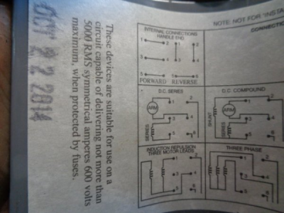
I posted the wiring diagram that came with the new switch. It is glued to the inside of the cover. Look here
1544021992910.png
.
 
so I have 2 questions now, since I am on my own.
Is it humanly possible to "test" each contactor to see if they are bad?

Next, lets make a "hypothetical" situation to solve.
Lets say ya have a wall that has 220v single phase power, then sitting on the ground under the 220v outlet plug on that wall, there is a new drum switch and a 220v motor. You also have a roll of the correct gauge wire sitting there with it along with the necessary hand tools and wire terminals and ya want to make this motor turn using the power from the wall

How would a qualified electrician make this happen? we know that 3 wires with a plug on one end (one white 110v, one black 110v and a green ground wire will be supplying the power. That's Line IN.
We know that the motor has 5 wires proceeding from it as follows
they are labeled
PE = green/yellow (ground)
U1 = black
U2 = brown
Z1 = black
Z2 = blue
We know that the drum switch has 6 terminals that wires and be connected to (plus a threaded hole for a ground wire.
contact.jpg

What wires need to be attached to where to make this motor turn?
 
I doubt any of the contractors are bad as you found the switch was broken, just like we found ours to be as well. It is just an issue of find the right sequences for the wire to run the motor.

You can test the contactors easily enough without power. You will test the terminals that I can see identified as U1,Z1,Z2 on the output side. The matching terminals above will make contact to relay the power to those below. Use a ohm meter or multitester, one lead on one terminal and the other test lead on the matching lower one. Press the Red plastic in so that the contacts are closed and if the meter shows continuity then go to the next set until all three on each contractor are tested. As for the pull in coils, there are two wires to it and the coil should show a reading in any position.
 
Last edited:
I doubt any of the contractors are bad as you found the switch was broken, just like we found ours to be as well. It is just an issue of find the right sequences for the wire to run the motor.

You can test the contactors easily enough without power. You will test the terminals that I can see identified as U1,Z1,Z2 on the output side. The matching terminals above will make contact to relay the power to those below. Use a ohm meter or multitester, one lead on one terminal and the other test lead on the matching lower one. Press the Red plastic in so that the contacts are closed and if the meter shows continuity then go to the next set until all three on each contractor are tested. As for the pull in coils, there are two wires to it and the coil should show a reading in any position.


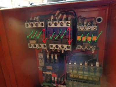
Ok, I tested the contactors for good measure , since it is pulled out from the wall.
All green checked contactors have continuity when the plungers are fully depressed.
The 2 end contactors (with the red arrows, wires marked #7 and #6) have continuity and lose continuity when
plunger is depressed.

Ya say "As for the pull in coils, there are two wires to it and the coil should show a reading in any position." Which are these?

DSC02910.JPG
 
If you go to the underside of the two motor contactors, I can see white wire with wire tag 0. There should another similar wires on the top side of the contactors. Check between the wire terminals that those wires connect. Usually the positions are called A1 and A2. The bottom one I can see are A2.
 
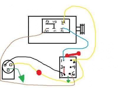
My special thanks to our Ulmadoc. We talked it over and went with this. Works excellent, so the case is closed and the answer to the problem listed. Here is the diagram to install a drum switch on a 1998 to 2008 Grizzly 4003 lathe.

Thanks again Mike for making this happen

Mutt

wires.jpg
 
Back
Top