Why can one not use their thread gauges to cut thread?

The problem with using an o.d. for measuring external threads or an l.d. for internal threads is that the unified thread standard has a flat on crest of an external thread and at the root of an internal thread. Unless that flat was accurately re-cut with each pass, any measurement of o.d. or i.d. respectively will not give accurate results.

It would be possible to cut an external thread by starting with an oversize diameter and cutting until the o.d. was equal to the major diameter + sqrt(3)/8 times the pitch, which is the diameter of an untruncated thread. For a 1/4-20 thread, this would be .250 + .0108 = .2608. The thread would be finished by turning the o.d. down to .250 which would create the proper flat.

A similar process could be used for internal threads. A slightly smaller hole could be bored and the threading tool used to cut threads until the i.d. was equal to the minor diameter - 7*sqrt(3)/8. For a 1/4-20 thread, this would be .250 -.0758=.1742. The thread would be finished by boring to the minor diameter or larger, e.g. tap drill size.

This procedure would be for a basic thread. Depending on the class of fit desired,an adjustment would be made to the diameters measured (slightly smaller for external or slightly larger for internal threading.
A copy of the standard thread geometry and an Excel spreadsheet giving values for the untruncated diameters for external and internal SAE threads are below.
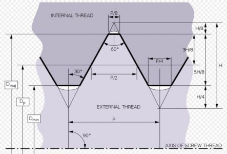
Thread Geometry.JPG
 

Attachments

  • Cut Threads by O.D. or Bore Dia..xls
    28 KB · Views: 10
This might explain it better
One-wire method.
In this method, one wire is placed between two threads at one side and on the other side the anvil of the measuring micrometer contacts the crests as shown in Fig. 13.14. First the micrometer reading is noted on a standard gauge whose dimension is nearly same as to be obtained by this method. Actual measurement over wire on one side and threads on other side = size of gauge ± difference in two micrometer readings.
This method is used for measuring effective diameter of counter pitch threads, and during manufacture of threads.
The difficulty with this method is that the micrometer axis may not remain exactly at right angles to the thread axis.
From the book Measurement of Various Elements of Thread (Metrology)
 
The answer is: sometimes you can get by using a nut to check your finished size and sometimes you can't. Almost everyone starts out with a nut but soon learns that A) sometimes there is no "nut" or B) what if the threads are on the other side of a part feature that can't be reached until the part is cut off?

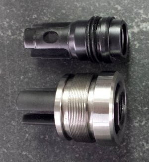
In the attached photo I had both situations on the stainless steel part. It had to be parted off of the bar on the left side as it sits in the photo, and there was no "nut". No one would want to part it off the bar without knowing if the threads were correct before hand, right? I couldn't run the part in the lathe the opposite way because I had to cut internal threads concentric to the outer threads.

The answer to the problem was to use pitch micrometers. Cutting the threads to the correct pitch diameter assured that the finished OD threads were the correct size. In the past I'd have just used thread wires (3 wire method) but I upgraded to pitch mics several years ago. By cutting your threads to the correct PD you know that your parts will always fit interchangeably with other correctly made parts.

2v2J3EJTZxAjwmD.jpg
 
B) what if the threads are on the other side of a part feature that can't be reached until the part is cut off?

It is not unknown in engineering to have to hold a threaded section on a part in a lathe and the correct size of collet will hold a correctly formed thread concentric for further operations, another option is to replicate the mating part in a sleeve, it's all fairly easy stuff to achieve, you just have to stop thinking about what can't be done and envisage ways in which it can,
Regards,
Nick
 
You seem to be using the term 'thread gauge' when you really mean PITCH GAUGE. They are completely different tools. A thread gauge will actually 'gauge' the fit of a thread,(as noted, an optical comparator/shadow graph is more accurate but very few people have them sitting around) A pitch gauge just verifies the pitch is correct which seems to be what your doing.
BTW, don't worry about it too much, 70% thread engagement in nut is normal in general engineering and is about 90% strength of 'full engagement. Majority of fasteners are over-sized for application wit very few exceptions. (only one comes to mind at present, axle adjusted bolts on many Honda motorcycles) They are often 7mm as 6mm isn't 'strong' enough and 8mm is extra material/cost- Japan has to import just about everything before they can re-sell it. Individually it isn't much but several million will be a substantial saving
 
Last edited:
I some analysis the one wire method as well as some measurements and it works well. Using only one wire and making a measurement with and without the wire will accomplish the same thing as using three wires. The measurement with the wire minus the measurement without the wire gives you the amount that the wire is above the thread crest. With the three wire method, the diameter measured will be the crest to crest measurement plus twice that amount. If d2 is the measurement with the wire and d1 is without, the measurement over the wires, as defined in the Pee Dee thread chart. "M" = (d2-d1) x 2 + d1 =2d2-d1. The pitch diameter can then be determined from the Pee Dee thread chart or from the equation E = M-3W+.86603/n where E is the pitch diameter, M is defined as above, W is the wire diameter, and n is the thread pitch equal 1/TPI.

The obvious upside is you don't need three hands to make the measurement as with the three wire method. The downside is that there are now two measurements instead of one and any measurement error is doubled on the d2 measurement, tripling your possible error.
 
It is not unknown in engineering to have to hold a threaded section on a part in a lathe and the correct size of collet will hold a correctly formed thread concentric for further operations, another option is to replicate the mating part in a sleeve, it's all fairly easy stuff to achieve, you just have to stop thinking about what can't be done and envisage ways in which it can,
Regards,
Nick

In my experience engineers spend all sorts of time dreaming up all sorts of ways to throw money at a simple solution. Down on the floor where the work gets done is where it gets sorted out. Thread wires are a little more practical for the home machinist.
 
That is the point I was tying to make as a hobby, resources can be better applied on things you need. A thread mic can be a big outlay for something that may not be used often even thread wires can be pricey. You may not always have a small drill or rod laying around to gauge threads but most everybody has access to some kind of wire, with it and a little imagination you can get the job done. I would rather buy something I'm going to use on a regular basis.
 
Back
Top