Will this fix the round column issue?

fatphatboy88

Registered
Registered
Joined
Mar 31, 2014
Messages
14
I just bought an old MSC version of the RF30 for dirt cheap and want to mod it already. I havent even gotten the thing running yet haha. I was thinking of removing all rotation out of the spindle head by building a 2x2" steel frame(blue part) and mounting some linear rails(red part) that guide the head up and down with some supports bolted to each side of the head(not pictured). Im pretty sure my buddy has the steel I can get for dirt cheap and the rails would probably be some SBR20 500mm ones off eBay with the bearing blocks. I figure I can find the right rails on ebay and get the steel cheap, that it could be done for under $150 and make this a much easier machine to use. I might even CNC it later on down the road.

Feel free to give any inputs you have. This is just a rough draft that I thought of on the way to work this morning.
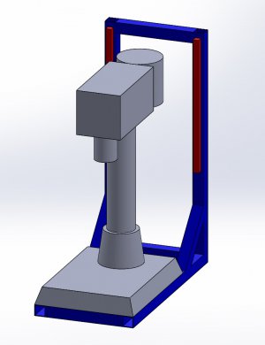
mill idea.JPG
 
I was thinking about something similar for my RF-40. I've seen posts of people using drill rod and oiled brass (bronze?) bushings as well.

Also, people put a cheap laser pointer on the head of the mill and draw a vertical line on the wall. The farther away the better, or some put a mirror to reflect the dot back. So, when you move the head up, you just move it side to side so the laser dot is aligned with the vertical line on the wall.

One other idea which I'm going to implement:
http://www.cnczone.com/forums/bench...chtop-colume-mill-drill-post-headaches-2.html
 
Alignment of the three vertical slides will be the diffficult part. You will need to build in some adjustability for those rails, so that you can align them with the column, or you will have binding. Good luck.
 
I just bought an old MSC version of the RF30 for dirt cheap and want to mod it already. I havent even gotten the thing running yet haha. I was thinking of removing all rotation out of the spindle head by building a 2x2" steel frame(blue part) and mounting some linear rails(red part) that guide the head up and down with some supports bolted to each side of the head(not pictured). Im pretty sure my buddy has the steel I can get for dirt cheap and the rails would probably be some SBR20 500mm ones off eBay with the bearing blocks. I figure I can find the right rails on ebay and get the steel cheap, that it could be done for under $150 and make this a much easier machine to use. I might even CNC it later on down the road.

Feel free to give any inputs you have. This is just a rough draft that I thought of on the way to work this morning.

There is a thread somewhere on this site (I looked but couldn't find it) that shows how the rack gear was pinned to the column and "alignment" blocks bolted to the column that capture the rack gear. If I remember correctly the author claimed .001" of repeatable rotational accuracy with this setup.

Tom S
 
I had thought about bolting the rack to the column but I wasnt sure if I'd be able to drill through it with a regular power drill once I got everything aligned. His idea is definitely simpler and a lot cheaper. If only I could notch the head assembly somehow and bolt a linear rail to the other side of the column and have the bearing block riding inside the head......

I like the power lift also. Now I just need to source a motor that I could use for it.

I think that your idea would be more rigid ( you could do both, of course). I'd want to connect the top of the frame to the top of the column in order to stiffen the assembly.
 
You don't need two rails; you only need one, and for maximum rigidity it should be as far away from the main column as possible. It should be triangulated to support it in the direction of load... your rectangular frame will tend to warp into a parallelogram, but a triangle in the same plane (with the rail in the center of an isosceles triangle, or the rail on one side of a right triangle) will be much more rigid.

Better than the round rails might be a flat rail with cam follower bearings on either side.

Some way to unlock it would be good, too... I tend to keep my vise bolted to one side of the table so I can clamp stuff to the table on the other side, and I swing the head back and forth depending on what side I'm working on.
 
I have been using a round column at home for a couple years now. I really don't see the issue with them.
1. try to make sure you can complete all machining steps without moving the head.
2. If you have to move the head reference a hole or other point so you can reset with your coaxial indicator, or a plug gauge etc.

It's not as rigid as a milicron but it takes up a lot less room, heck at work we sometimes have to move the work mid job even on the big machines. We simply plan for it.

Steve
 
Back
Top