Wiring Vevor VFD Control Panel in Remote Location

blueacre

Registered
Registered
Joined
Mar 19, 2017
Messages
15
I just purchased a Vevor VFD for my lathe. It is a model A2-8075 - 7.5kw 10HP. The literature says the Smart Digital Display (control panel with stop/start and other push buttons plus LED display) can be removed from the VFD enclosure and mounted remotely. I downloaded the installation manual and there is no info on wiring the Smart Digital Display remotely. I contacted Vevor and they confirmed remote mounting can be done, however they said that they do not supply the wire to do this and couldn't give me any info on the type of wire required like number conductors and gauge of wire, shielded or not. Also no info on the type of wiring connectors at each end.

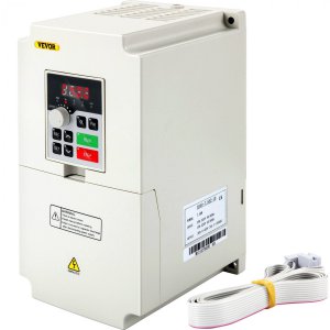
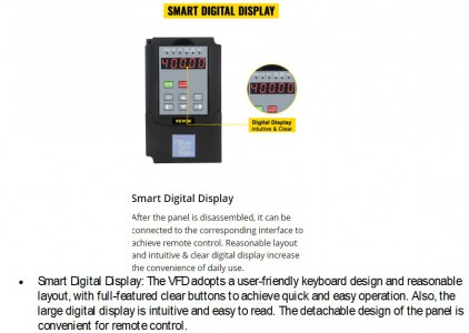
See copy of info from Vevor website below.

If anyone has more info on the cabling requirements for remote mounting of the Smart Digital Display I would appreciate hearing from you.

Remote panel 1.jpg
 
Does the remote panel plug in to the main unit? Can you post a picture? It's probably a standard plug type
I'm thinking it's most likely a ribbon cable which could be purchased from a computer supply house or Amazon
This Vevor shows a ribbon cable:
vevribbon.jpg
H100-7.jpg
 
Last edited:
Sorry I should have mentioned that I just ordered the VFD yesterday - supposed to be here in a couple of days and will update with more info when I get it. I thought maybe someone had "already been there done that" and could point me in the right direction so I could buy whatever is needed so I can start installing VFD when it gets here

I see other manufactures refer to a communication cable like RS232 or a cable with a plug similar to an RJ45 computer ethernet cable.
 
I put mine in a box with a glass front so I can see the VFD inside.
 
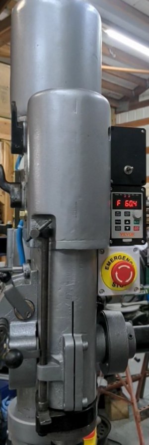
I did it the cheap way with the arboga drill press.
Plastic box cut out and two 4 conductor shielded cables.
Chopped off the quick connect at the main unit and then soldered shrink tubed the wires.
added the quick connect at the display end so it can be somewhat modular.

This is the 5 hp model , looks to have less features and conductors than the more powerful 10HP model. Still working on the one handed start stop switch. I thought Vevor would want momentary contact switch like the key panel but looks like they want a full time short while being in operate or stop when triggered remotely from trying a momentary contact style switch.
 

Attachments

  • PXL_20240124_210405687_exported_661_1706206233469.jpg
    PXL_20240124_210405687_exported_661_1706206233469.jpg
    60.4 KB · Views: 9
  • PXL_20240123_041731841.jpg
    PXL_20240123_041731841.jpg
    258.3 KB · Views: 7
Last edited:
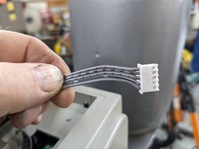
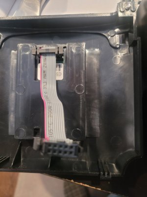
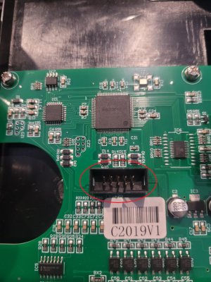
My Vevor VFD was delivered to day - looks like a reasonably solid built unit but time will tell. The smart digital display panel snaps into the main housing front cover - it is a real tight fit with a plastic locking tab - I couldn't seem to get it out - didn't want to force it and break the plastic so I just removed 2 screws to take the front housing cover off for now with display panel still attached. I was able to access the cable connections - it is a 10 pin flat ribbon cable similar to desktop computer cables - plugs are 10 pin in 2 rows of 5. See pics attached

I don't plan to use the variable frequency to vary the chuck speed - just use the lathe gearbox - that way the input shaft always runs at the design speed and the gear box lubrication pump should work as designed. For that reason I have decided its probably better to leave the display panel on the VFD unit and mount it in an enclosure with a window so I can see the display from the lathes operator position.

For controls at the lathe I will build a push button station to mount on the lathe and wire that back to the VFD - main controls will be start / stop buttons and selector switch for rotation direction.

I haven't decided what I should do for power to the VFD - I was thinking I could put a magnetic contactor ahead of the VFD to switch the power on and off to it. If I did that I would put a separate start button on the panel at the lathe to close the contactor and power up the VFD and use an auxiliary contact on that contactor to keep the circuit energized once the power on button is pushed. An emergency power off button wired into that circuit would open the circuit and shut off power to the VFD.

Does anyone know if it is OK to turn off power to the VFD while the motor is running - will the motor continuing to generate voltage/current feedback to the VFD as it coasts to a stop cause any problems for the VFD ?


ribbin cable 2.jpgribbin cable 1.jpg
 
I think it's best to not have the motor running when you shut the unit down.
Many people just leave the unit on all the time. I believe it's harder on the VFD to keep turning it on and off
 
A motor will self generate power as it slows down and there is some charge in the capacitor bank that can keep the VFD powered for minutes after the power is disconnected. They also indicate to wait at least 5 minutes after turning off a VFD and checking the voltages before handling any of the connections. There is also the added factor that frequent switching on-off-on of the VFD can damage/destroy the inrush circuitry, and I have seen this happen on several VFD's.

It is not advised to shut down the VFD while the motor is running, and it will also slow the braking time. An E-Stop at the machine is typically designed to shut down the machine/movement as fast as possible and then prevent the potential for restart. Also in some cases it is also designed to prevent the output section of the VFD operating even on power up (STO). One always needs to have some level of redundancy, as well as hierarchical programmed inputs on the assumption that a run or stop switch fails. How this is implemented is based on the VFD, programmable inputs and control system operations, whether this be solid state, relay or other type of controller system.

My approach has been to typically have 3 levels of interlocks and controls for an E-Stop, the first is at the relay level that issues the commands has a power latching relay that drops out for any fault/E-Stop, this prevents the other relays from operating and also interrupts the VFD run signal. The E-Stop is mechanical redundant switch which stops power to the control system, also interrupts the VFD control circuit and turns on a VFD input programmed as an E-Stop (on some VFDs). The programmed E-Stop input is set for the fastest braking, and also supersede any other active run command and often requires a VFD reset as well as the run command can not be active. Other stop systems also have a similar redundancy. If one wanted to take this to the next level you could add a STO circuit once the VFD had a 0 speed output detected using one of the relay programmed outputs.

I recently had the experience where an individual with a lathe (1340) used the STO function for the E-Stop and then was mentioned that the chuck kept spinning for a long time after he pressed the E-Stop, the STO circuit prevents the VFD output section from operating and therefore there has no VFD braking. He rewired it back the way I indicated.

As far as powering the VFD, most of us do not use our machines on a regular bases, so leaving the VFD on all the time is not warranted (exception may be very cold climates which can damage the capacitors). I usually recommend if you are going to be using a VFD powered machine through the day, then turn it on when you start the day, and turn it off at the end of the day. This is also a safety precautions if someone else had access to your shop/garage or you have little ones running around. Frequent powering on/off cycling of a VFD will cause it to fail sooner, using a contactor to tun on/off a VFD is OK, and but not as a safety E-Stop in my view. Almost all VFD's have programable features which prevent a VFD restart with an active run command on power-up.

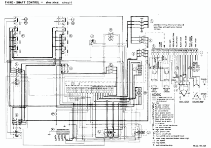
To get back the lathe at hand, my understanding that the application being considered for this is a Colchester Triumph Mk 1/2 round head lathe that is setup for 575V. I have looked at similar lathe models and the do not use a simple spindle switch setup/control system, so adapting to a VFD control system would be more challenging and in most cases, a complete replacemnt control system, and the Vevor A2 series does not support most of the common programming and control options discussed. My advice would be to see if the lathe can be rewired for 240VAC 3 phase, repalce the motor with a 230VAC 3 phase model, all of which woul also require changing the fuses/heaters, and then powering it with a Phase Perfect or RPC if you wanted to keep the functionality of the current controls. Would need to know more about its operation, but I think one would be beter off doing a complete replacement VFD control system for full functionality. If your lathe uses a clutch drive system and has electro mechanical brake system already built into the lathe then it is a bit differnt.
1706227130136.png
 
Thanks for the comments-
to clarify the normal lathe startup and shutdown would be to use a start and stop button wired to the vfd control input terminals but the vfd is still always powered on. Only if the emergency stop is pushed whike motor is running would the motor still be turning when the vfd power turns off. In an emergency this could stop the motor quicker rather than going through the normal vfd deceleration steps.
Once the motor Is turned off with the normal stop button the emergency stop button can be used to turn off power to the vfd. I thought this might be better if not used for a long time and help to prevent damage from power surges due to lightning or other reasons.
 
This is not a correct statement as I indicated, the fastest way to stop a lathe chuck (other than a mechanical means) is when the VFD remains powered, you execute an emergency stop command while power is still supplied to the VFD. It also requires an external braking resistor and you are still limited by the potential energy stored in the system. If you disconnect the VFD power you slow the stopping time of the VFD, I know this from direct experience and the stopping time can be up to 3-4X longer. Also things like DC injection if used will not work if there is no power to the VFD. Using a remote contactor to power on/off the VFD for general use as a remote/remote safety is fine, you can use a latching circuit on the contactor to keep it on, this also requires an always on power source to activate the contactor. This often used either where there is not a power disconnect switch at the machine or you want to be able to turn on the power remotely say from the front panel using a low voltage system.

The purpose/action of the E-Stop depends on the intent of what you want it to do under what conditions. There is also a difference between remote often use dto lock-out the machine from operating vs. an immediate stop, including destructive means.
 
Back
Top