- Joined
- Aug 29, 2016
- Messages
- 121
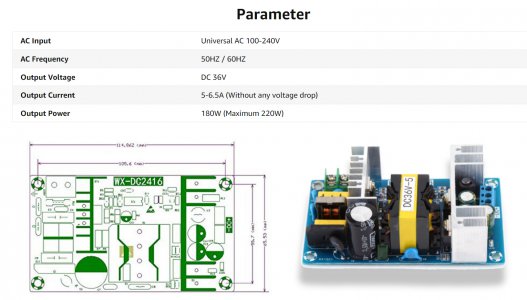
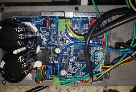
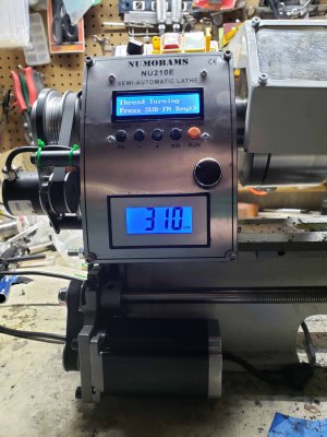
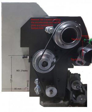
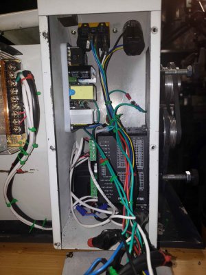
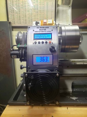
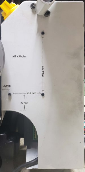
I just got the kit today and installed it. I consists of a standard stepper driver, a 36v 5a power supply, a new faceplate, and a small controller with a display. There was no documentation at all. I wound up drilling some extra holes to mount the electronics. It is not an easy or obvious fit. The connectors are not made for the high vibration environment of a lathe. You need a m6x1.0 tap, drills and an assortment of m3 screws nuts and washers.
It works and is quiet without change gears. It seems to be geared to threading. I could not see how to cut a length and then loop for deeper cuts. It would seem that the way to do this is use a fine thread. It does do looping for threading.
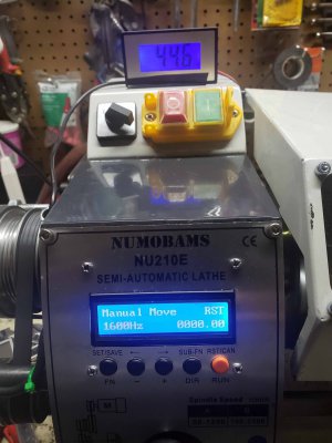
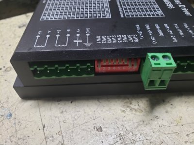
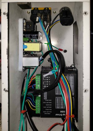
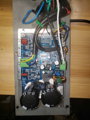
When I figure out how to use it I will post a video. You can program the encoder and stepper pulses, so this should be adaptable to any other setup. There is no documentation so I took pictures of the connectors just in case the wires come loose.
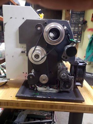
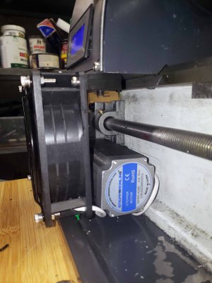
It uses a NEMA 23 motor 110 mm long.
It works and is quiet without change gears. It seems to be geared to threading. I could not see how to cut a length and then loop for deeper cuts. It would seem that the way to do this is use a fine thread. It does do looping for threading.
When I figure out how to use it I will post a video. You can program the encoder and stepper pulses, so this should be adaptable to any other setup. There is no documentation so I took pictures of the connectors just in case the wires come loose.
It uses a NEMA 23 motor 110 mm long.
Last edited: