X-Feed Rates on PM lathes

B2

H-M Supporter - Diamond Member
H-M Lifetime Diamond Member
Joined
Sep 2, 2018
Messages
856
Hi Folks,

Have others measured their X-Feed rates on their PM lathes.

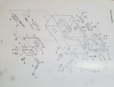
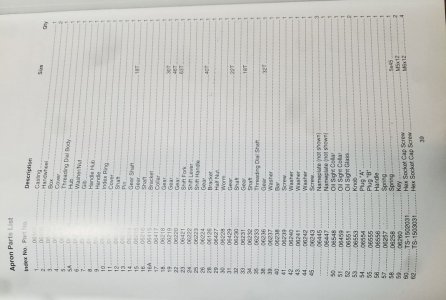
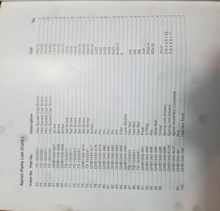
I have a PM1440GT and it says on the front gear panel that the ratio of the Power Feed and the X-Feed rates are simply 2:1 (or 1/2) . I think this is the common statement made for many lathes. However, I have made a quick attempt to measure these rates on my machine and I get a number more like 3.14:1 not the factor of 2. I think the x-feed part of the table on the lathe is incorrect. It is probably not something that most folks often even question as the distance traveled via the manual handle seems fine. But when I look in the manual at the apron gear box I cannot make much sense of it. I certainly cannot predict the Feed rates from looking at it. The manual at least list gear dimensions, but I cannot tell how they are connected or even if they are all there... from the illustrations in the parts section.

Has any one taken the gear box (PM1440GT) apart to see if the drawings are close to really representing the gears? Maybe some one else can figure out the gear arrangement and my lack of 3D imagination? Has anyone measured the x-feed rates? The table value for the Power Feed rates do seem close.


Dave L.
 
My lathe is a PM10-30, New last year.

Its' interesting you should bring this up. I'd been wondering, hadn't thought about putting an indicator on it. I just did, left and right movement (I dunno x and y and z on a lathe) in whatever gear set up I have for feeds, (ABC in C for the greatest movement) showed .0092, in and out showed .0021 (Starrett dial indicator, reads in tenths. ) That's 4.38 to 1 ratio. Only direction of movement changed, no gears where changed in this experiment. That surely isn't 2:1.
 
I just checked my 1236T, it’s supposed to be 1:3, but measured to 1:3.25, that’s close enough for government work. Maybe yours is supposed to be 1:3 as well and they just miswrote it?
 
Thanks folks, So I am not going crazy. Yes, government work and it may not matter much to others, but do most of us even question the lathe plates? I suspect that the 1:3.25 is more likely correct and that the 1:3 is just how they truncated the numbers. Surely it is more exact and repeatable than just one digit!

Both the front panel label/plate and the manual for my PM1440GT says my x-feed rate is suppose to be 1/2 of the Power feed (z-axis). Just to be sure I just went an remeasured it. I have a counter connected to my spindle and a DRO on both axis so I used them. If you want to understand how I put that in to my VFD control the posting is linked below. A link to my VFD system and its counter is noted below.

I am going to set the factors of two on the gear box at 8x so as to cut the highest TPI or the slowest feed rate. This makes the spindle turns higher and slows down the feed. Then I will make a long feed run so as to get a high count with lots of digits... and see if I can get the numbers to higher accuracy. I have a DRO on the machine and counter on my spindle so I will just turn it on and wait until it trips the proximity sensor. Unfortunately there is no proximity sensor on the x-feed. I will have to watch it more closely!

adding a counter to my VFD converted PM1440GT

Dave L.
 
Some of this discussion was occurring on an unrelated thread so I am moving it here.

Dave, on my Metal Max MM-1340LB (China-made Jet/Enco belt drive clone) the manual states that the carriage feed rates are 0.0036-0.1005 and the cross-feed rates are 0.0012-0.0345. That is pretty close to 1/3.

Hi @Provincial

Thanks for the information. It is good to know that not every manual says the ratio is 2:1. From above you will see that your value is also found by others.

Yes, I would be interested to see your manual info. I googled your model number + manual but did not get hits. But before you go to the trouble of photographing them... Perhaps they are the same as others... I did find a JET manual, but do not know if this is your lathe (see below).

You may be interested in looking at the on-line manual for the PM1340GT (link HERE ). It may look the same as yours? In the PM version of the manual, near the end, are illustrations of the drive train for both the main gears as well as the apron. Unfortunately in the parts list they do not give the tooth count on the gears. I do not have the 1340 but a friend of mine does and he made a quick measurement and he said he did not the 1:2 ratio either. I have the PM1440GT (link HERE ). You can also look at its manual and you will find that the apron gear illustration appears to be the same as the 1340 illustration. In the PM1440GT parts list many of the gear tooth count is provided. PM removed the tooth count from a couple of head stock gear assemblies of the PM1440GT online manual, but I happen to have the printed manual that came from the factory and they are listed there. Also, I found an old looking manual on-line for the Eisen LD-1440E (link HERE )and it appears to be the same and is for both the 1340 and is more complete. It is also for both the English and Metric versions. Perhaps it is the same as yours?

There are several problems in trying to read these illustrations. One is that the parts lists never seem to give the TPI for the lead screws, the worm gears(not important), and the RACK on the bed and sometimes I think they are just incomplete. Fortunately you can simply crank the handle a few times on the X-Feed and measure the distance traveled to get that lead screw. On the 1440GT (English) it is 10TPI. I spent quite a bit of time trying to understand the main gear box in my 1440GT. I finally got the numbers to all work out, but I had to physically re-arrange the positions of some of the gears in the illustration! Even after all of that some of the gear positions would not clear each other as you moved the levers!

I really am coming to the conclusion that some of these illustrations are rather generic and may not even apply to the actual lathe that one has! Perhaps the machines evolved and the manuals never kept pace? I am not for sure what one does if he needs new parts! I may not get around to spending the time on it, but I looked at a JET version of the 1340 and 1440 (which may be yours?) and they are not laid out the same, but may provide insight into parts that are missing in my own lathe manual. It is HERE . Also, this manual has a more extensive table of TPI and feed values at pages 16-17 and they support the feed rate ratio of around 3:1, ... not exact.

By the way, my solid state VFD conversion is HERE. Others have ask me if I have made my hand wired electronics board in to a PCB that could be made available. I am thinking of doing so. It seems that a lot of folks are not familiar enough with electronics design to build the hand made board with confidence. I am not really interested in doing conversions and selling them to folks, but I am willing to provide advice and encouragement on my design.

Dave L.
 
Last edited:
I kept it simple and put it in the highest gear and rotated the chuck by hand 10 times and then took the average after taking out the backlash. The Z feed was dead on and the cross feed came out to 1:3.25 for the two feed rates I checked.

I checked the PM manual for this lathe and it shows a picture of the feeds table and the cross feed should be 1:2, but the plate on my lathe shows 1:3. I'm guessing they made a change somewhere along the line and never updated the manuals, and you happened to get one of the older thread and feed diagrams.
 
Hi Guys,

Thank you for your efforts.

When I measure my ratio using ~ around 700 turns of the spindle, I get: 1:3.1343 Could it be that your number is really more like mine or are you confident in the .25 part of your number? However, I have some more work to do before I am totally confident of my number, it is conceivable that I have some noise in my measurement of the number of counts, ..... If I were getting extra counts that would drive my number down a bit. I will try to check on this a bit more... later.

Dave L.
 
While I can't speak to your lathes, I can say that having worked as a tech writer in the past, it owuld not suprise me at all if someone simply didn't care enough to update the user manual. It's unfortunately far more common than it should be.
 
I’m very confident in mine. I set an indicator against my cross slide, turned the chuck until the dial started moving, zeroed it out and made a mark on the chuck, then spun it ten times and measured the displacement. I did that for two different feed rates and it came out the same. I tried using the gear ratios to verify it, but I was way off, so I think I need to spend more time figuring out how the gears engage in the apron.
 
B2, Here are the photos of the Metal Max manual pages. I included page 7, which has the specifications. I didn't include the cross slide pages, since there is no gear tooth information there.
Cover.jpg
Page 7.jpg
 

Attachments

  • Page 36.jpg
    Page 36.jpg
    76.4 KB · Views: 74
  • Page 37.jpg
    Page 37.jpg
    106.7 KB · Views: 83
  • Page 39.jpg
    Page 39.jpg
    164.8 KB · Views: 77
  • Page 40.jpg
    Page 40.jpg
    104.1 KB · Views: 77
Back
Top