Yet another 1ph 220v reversible motor and switch wiring issue

tjm_ar

Registered
Registered
Joined
Dec 6, 2018
Messages
20
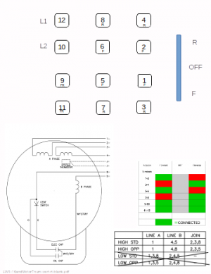
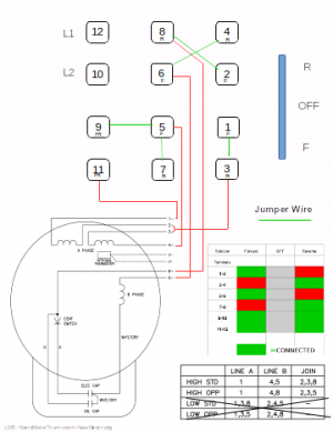
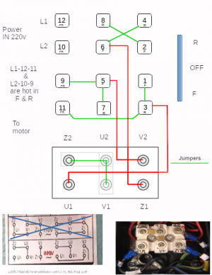
I'll dispense with the background issues (unless you really want to hear the story) and post my wiring diagram both for checking and for a better way to do it. There's so many switch types and incomplete switch and motor information that it's difficult to reach a solid conclusion for a wiring setup. That leaves us with connections that are probably better than a best guess but maybe not quite the perfect setup. A final setup that runs and doesn't produce smoke is probably OK, but? I really don't see any other way to make the start winding run on 110v and still retain the reversibility. My diagram is there along with a blank worksheet if anyone has either a correction or a better/easier way to do it. My diagram uses 5 wires from the motor to the switch. I've seen diagrams with 3 and 4 wires to do the same thing but I suspect it has to do with the type of motor and windings. I'm far from being a motor expert so if you happen to use my wiring methods then you're on your own. Pics and pdf included. For info, Grizzly G6760, alias X6320A, Jet 836, Enco 10-1525.

Thanks for taking a look
 

Attachments

  • LW5-16andMotorTnum-vert-rt-NewMotor.pdf
    228.2 KB · Views: 14
  • LW5-16andMotorTnum-vert-rt-blank.pdf
    210.3 KB · Views: 2
  • LW5-16andMotorTnum-vert-rt-blank.png
    LW5-16andMotorTnum-vert-rt-blank.png
    35.7 KB · Views: 18
  • LW5-16andMotorTnum-vert-rt-NewMotor.png
    LW5-16andMotorTnum-vert-rt-NewMotor.png
    40.1 KB · Views: 20
Last edited:
When dealing with 120/240 volt motors, the usual practice is to place the two run windings in parallel(120v) or in series(240v). For 240 volt connections, the start winding will be connected at the "center tap", the common connection for the run winding. For 120v connection, the start winding is connected in direct parallel with the run windings. Reversing the two start winding connections will reverse the direction of rotation.

Looking at the connection diagram alone is meaningless to me right now. I have to study that diagram with the motor to make good sense of the overall connections. It does look to be a usual dual voltage reversible motor. It's my mind that is in left field.

The primary question here is whether you are connecting for 120 or 240 volt supply. For 120 volt supply, wiring in the reversing switch will be to the diagram for whatever switch you are using. For 240 volt connection, there are 2 live wires feeding the motor, but only one line contact. Meaning that with the usual reversing switch with one line contact, the other will be connected without a switch. Live all the time. That would require a two pole switch somewhere to be perfectly safe.

In my case, I don't have one. And don't worry about it. But I've been an industrial electrician for over 50 years and am very particular about grounds and other electrical safety.

.
 
Thanks for the reply. I'm working with the higher voltage wiring only, 208-240v. Mine is actually 240v.

Both lines are disconnected from the motor in the OFF position, and both lines are connected when switched to either the Forward or Reverse position. No power makes it past the switch in the OFF position. The colorful diagram and the numbered switch connections with the small F or R in the block show which switch terminals are hot in the Forward or Reverse position.

This is my backup motor and I'm waiting for a new LW5-16 switch to actually make all the connections and give it a try.

My installed and working motor is a replacement that has the Euro/Chinese terminal labeling and config, if anyone can figure out what that means on any particular labeling day. I stuck with the label on the motor and configured the switch accordingly. It works in forward and reverse using only three wires from the motor to the switch. I'll post that connection diagram if for nothing else but to add to my own confusion. Your confusion factor may vary. I have no idea which wires go to which coils/capacitors and I don't plan on disassembling a working configuration to find out unless I develop a serious brain malfunction. There's probably a U-V-W-Z configuration diagram somewhere that matches this motor but I haven't found it yet. It works with three wires, but I can't explain it. Use the switch legend from the first post pic.
 

Attachments

  • LW5-16andChineseMotor-vert-r-YL90Lfinal.png
    LW5-16andChineseMotor-vert-r-YL90Lfinal.png
    114.9 KB · Views: 21
  • LW5-16andChineseMotor-vert-r-YL90Lfinal.pdf
    156.9 KB · Views: 3
Last edited:
here is the stock wiring diagram for my shenwai sw900b 1236 lathe, (it has been changed to VFD and a marathon 2hp motor since)
the lathe was capable of running 220 or 115v with the change of a couple jumper wires at the control transformer
it has a 4 wire momentary switch control system
1591219449803.png
 
On 230 volts you should only need 3 wires from motor to switch- let me cogitate on your diagrams and I'll post a sketch for you
-Mark
 
On 230 volts you should only need 3 wires from motor to switch- let me cogitate on your diagrams and I'll post a sketch for you
-Mark

THAT'S what I'm looking for. Feel free to print and use my switch and motor template if you like, but I'm not seeing any other way to run the start coil at 120v. This is a single phase motor.

Thanks,
Tony
 
Last edited:
Hi Tony- this should work
I suspect your red/green switch table was incorrect, I pulled one off the web; you should check that your switch matches it using a continuity tester or ohmmeter. If your switch really is as you posted I will need to modify this sketch- let me know
-Mark
12Pswmot230.jpeg
12polesw.jpg
 
Last edited:
Tony: If your switch is really as you posted then you would connect it like this: (1,2,3,4 not used)
12poswmot230X.jpeg
 
Thanks, was just in the process of figuring out how this actually connects for both switches. In effect, we're only changing which line gets connected to T8, but I'll admit I'm unclear about how or why that works. The other motor I already have running correctly with the LW5-16 and only three wires had a diagram on the plate that I was hesitant to use but it actually works perfectly. It's labelled in the Chinese/Euro format, the connections are made internally and there's no labeling on each wire. That pic is up there in my second post.

Anyway, my switch contacts are correct and verified with an ohmmeter. No problem. My switch is a LW5-16 and the one you have posted is an LW28. There seems to be an endless number of configurations for all of the LW series drum switches that I've found. I already have a new LW5 on the way and I'll check it's configuration to make sure it's the same, too. I can use either and I don't mind getting the LW28 as it appears to have a higher amperage rating.

My new switch won't be here for a few days but I'll post the results with schematic and pics when it's done. I'm sure that this thread should clear up a lot of other wiring diagram posts for drum switches and reversibility.

Thanks for the assist.

Tony
 
You're right about the endless number of different switches, there also seems to be an endless number of people confused by how to wire them :)
-M
ps in this 3 wire configuration moving T8 from one line wire to the other gives the reversing function, and the start leg only sees 120 volts since it connects to the midpoint of the two run windings
pss you can swap T8 and T5 if the motor rotation is backwards from the switch handle
 
Last edited:
Back
Top