Yet another Rockwell/Delta metal/wood bandsaw restore

Grandpop

H-M Supporter - Sustaining Member
H-M Platinum Supporter
Joined
Jan 20, 2016
Messages
173
I have asked some questions during my recent rebuild (thanks Rich for your help), and am now almost finished the effort. Posting my rebuild of a 28-300 / 28-380 / 28-390 bandsaw. Different documents show the enclosed base version of the 28-300 basic saw as 28-380 and 28-390, so not sure which one it is. Saw is marked 28-300, but that is without a base. Maybe someone on here will understand the difference in model numbers?

I bought this gal back in May at a local on-line only auction for $60. The only description said something like “never been under power – no info”, with 3 poor quality photos. Could see the metal cutting gear reduction shaft was there (no pulley) so knew it was the metal/wood version, and could see the upper blade guide was MIA. As I had just finished a major rust repair to the deck of the Gravely and was extremely tired of cutting 1/8 sheet metal with jig saw and grinding discs, I decided to take a chance on it.

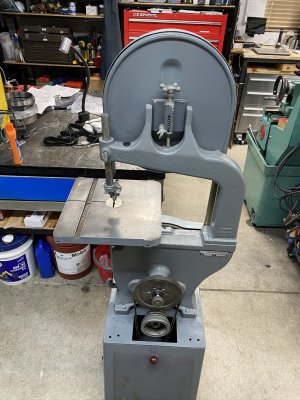
Here she is before I unloaded it in the driveway. Let’s just say she was rode hard and put away wet frequently. PO must not have been very mechanical, as could see lots of things jerry rigged and or messed up after scraping away worst of the crud.

1594858532053.png


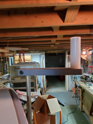
Hate this tension adjusting knob in center of rear door, my fat fingers make it hard to turn there. Will raise it up above the door during the rebuild.
1594858580529.png


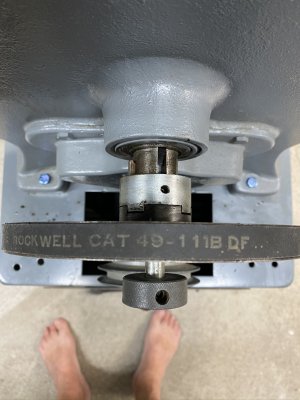
At first exam, this 1974 model 28-380 was missing the upper blade guide and guard, both 4 step pulleys were missing, the blade tension adjuster rod and nut were both stripped, the high/low speed clutch was frozen, the motor was 3450 rpm and not working (hums), missing lots of little things and hadn't even gotten into it yet. Checking some prices for used parts on the web and this $60 purchase was starting to look like it needed $700 in parts, which is what a decent one sells for locally. Basically made it look like a parts machine! After receiving some coaching on here, including lots of VERY helpful information locating manuals and p/l, I decided to try to resurrect it, as at least I would know exactly what I had when I was done (and I can't go anywhere anyway, so needed something to do).

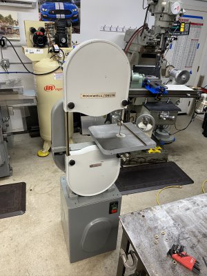
Spent better part of last 8-10 weeks researching, tearing down, cleaning, and figuring out how it was supposed to work. Then buying LOTS of parts, repairing everything, all new bearings/seals, filing the burrs off of every casting and sharp edge, making a fair amount of missing/buggered up parts, painting (even tried to match the original 2 tone paint job) and reassembling it. A new HF 1800 rpm 1 hp motor, new switch and wiring, some more head scratching, and she is now proudly back among the living.

First the tear down. It only takes about an hour or two to turn the bandsaw into piles up rubble.
1594858724498.png

1594858738340.png

1594858748152.png


Started with the simple repairs while waiting for all the ordered parts. The upper wheel mounts to this stud, and it pivots on a shaft in the hole to allow for blade track adjustment. The housing hole was .021 looser than the pin, so after a bit of head scratching, decided to cheap out and make this .010 shim. Was able to get the pin back in pretty snug. First upgrade finished.
1594858810901.png

1594858819323.png


First batch of cleaned and straightened dark machine gray painted parts, then the stone gray upper/lower doors (closest to garage door, can barely see the 2nd upper door sideways behind first one).
1594858864494.png

1594858873567.png


One of next things fixed was the stripped tension rod and nut. I did not like turning this knob in back in middle of the door, so bought a 3/8-16 x 13” long McMaster grade 8 bolt to raise it above the upper door like the newer models. Set the bolt up in the lathe, made the threading undercut, picked up the old threads, then cut the new ones to 4.5 inches long. Turned it around and turned the hex head off so old knob could be pinned onto new bolt.

1594858903527.png

1594858912125.png


Put it back together with the old knob on new longer bolt above the upper door. Was way better than before, but still took too many turns to go from loose to tight (8 turns?).
1594858931227.png

1594858939390.png


Decided to take the knob off and made a handle for it from piece of 1/2 x 1 x 5 scrap, a rusty shoulder screw, and then made a new rotating handle for it out of UHMW. Could have bought a $67 plastic handle from McMaster, but no fun in that. Much nicer now! Takes a few seconds to adjust, not minutes.
1594859256615.jpeg


1594859281047.png


Hard to see, but the end of the old tension screw just pushed right against the casting. I drilled a 1/4 hole, then turned a 1/2 ID bowl shaped holder for a pair of $5 Amazon flat thrust bearings. Now the end of the screw pushes against the trust bearing, so the tension handle turns very easy, even under load.

1594859343712.png


One can buy the standard $30 Danly yellow die spring to replace the crushed worn out original spring, or buy the $18 ebay one, or can buy the $9 green Raymond equivalent on McMaster. This was the gold one I ried first, but have the green one in there and works better. No picture of it, but I made a new nut out of )1 tool steel that was 1/2" thick. Heat treated it and installed it. Another good upgrade.
 

Attachments

  • 1594858965378.png
    1594858965378.png
    345.5 KB · Views: 286
  • 1594859198960.png
    1594859198960.png
    345.5 KB · Views: 299
part 2

I was still waiting on last few things (v-belts, metal blades and 2nd attempt at stronger tension spring), so I turned to the missing sheet metal parts/covers. It had the upper guard for the rear pulley attached but was missing the lift off door, was missing the lower rear door entirely (but has the latch inside the cabinet), was missing whatever the cord keeper was supposed to be, and was missing the upper front blade guard.

I could find very little information about the base cabinet parts (did find the p/l) or photos of them to try to copy, but I did find these 2 photos below that show the 2 missing doors. So these were the basis of the parts I made to replace them.

1594860199560.png


1594860215538.png

The red arrow is what the p/l calls the “Stop Strip”, and inside the cabinet attached to the 2 red screws in 2nd photo are the “latches.” I am guessing that the stop is a rubber strip, and the catch is some kind of c or h cross section hook that holds the door open at the angle shown, then you just lift the door off? So that’s what I tried to do. Above photo (right) looks like there is supposed to be some king of foam/rubber edging on there, maybe to stop vibration? So that is the way I made mine, just used a piece of 1/8 rubber.

The green arrow (above photo) cord keeper is another mystery. This is the only photo I have found anywhere that even has something in the hole, all of the others are just blank holes! Unlike the above photo, my saw has a screw hole each side of the opening, so thinking it may have been a wood block? So that is what I made, a 2 piece block; large piece has the hole and slot for the cord, then smaller T shaped piece to clamp the cord at bottom of slot. The block assembly then screws to inside of the cabinet. Didn’t get a picture of it prior to installation.

I made the upper pulley door cover, half hinges and door mounted striker. Mig welded the 2 little hinge halves to the door. Was a struggle bending the .075 sheet that I had for that 11” high door, but after beating and filing came out good enough for me. The hinged door hanging in center, the lower door on the right, then new brackets hanging on chain in center, the old shield and electrical cover on left.
1594860276924.png

1594860287132.png


The table has a slot to get the blade in/out, and then uses a tapered pin to hold the ends of the table into alignment. I took a 3/8 bolt and turned the matching taper onto it; that missing part solved. Also took a piece of 3/16 thick scrap plate and turned a new steel center hole blade guide/filler. Those 2 items were $50 if I had bought them, and instead only took maybe 3 hours to make.

1594860313816.png


1594860324865.png


Made a couple of 5/16-24 x 2” long set screws by threading fine thread grade 5 bolts all the way to the head, cutting the head off, then cutting a screwdriver slot where the old bolt head was. The shiny one is new, and other new one is under the table for the table rotate stop. Also made these 2 missing knurled blade guide fine adjuster knobs; they move the blade guide bearings forward/back.

1594860374576.png

1594860384076.png


Made this lower blade guide assembly (part with the 2 small bearings). These guide assemblies are available for $80 bucks online, and bought one, but it didn't fit, so copied it (sort of). 10 bearings were only $8 on Amazon. Took me 4 hours to make the T shaped base (welded), the 2 eccentric cams for the bearing mounts, and a screw to tighten the back side of the cams so they won’t move when rotated against the blade.

1594860512041.png


1594860521661.png


I was able to find lots of photos of the missing upper blade guard, and can buy an aftermarket one as well; it attaches to these 2 screws. I will be starting on that one next. Think I am going to have to buy some more .060 sheet stock first to make the bends easier than the .075 was! The guard has to come off every time you change the blade, so thinking I want some kind of threaded knurled knob instead of the factory screws. That way I don’t need any tools to change the blade.

Made this little chunk of scrap steel that tightens onto the top of blade guide vertical height adjuster. Good base for the cheap $10 reading light from Amazon, and it puts out enough light. Will have to see how well it holds up to vibration.

1594860622370.png


Last thing made before final assembly: 2 steel 1-1/2 diameter knobs for the back doors. I do not have a ball attachment, so did some simple trig to determine touch and go dimensions for the 45, 22.5, and 11.25° angle set-ups I made each side. Filed to suit when done and polished with 2120 Emory paper. The end of the ball is finished by screwing onto the tap, locking in place with a nut, and chucking on the tap. Easy to put the 11.25 angle on and blend it in.

Here she is today. Four new large black door knobs from McMaster. Love the paddle stop switch!
1594860865287.png

1594860878049.png


1594860893364.png


The way this high/low works, the knob at end of large pulley slides an inner shaft that is pinned to 2 clutch halves in/out on the main shaft. With the knob pushed in, the inner clutch half engages the gear reduction unit (short belt from motor), so saw runs at metal cutting speeds. The large pulley is disengaged and free wheels. When the knob is pulled out, it disengages the gear reduction unit and outer clutch engages the large pulley (long belt) for wood cutting speed. No tools for blade speed change.

1594861006262.png


Last thing left to mess with are the 2 low speed stepped drive pulleys. Each was 4 step from factory. Original motor pulley is no longer made, and upper one is available but $187. I bought this pair from McMaster to get it up and running (about $70/pair), and while they are close to the factory diameters, the pulley diameters are not quite same as factory. Factory pulleys are set up so same belt length works/fits in each pulley step; can leave the high speed wood belt on, and just change the slow speed belt to get desired metal speed. With the McMaster pulleys slightly off, that means when you change to next step the belt length needs to be slightly different on each step. I think long term I am going to have to make a pair of new solid pulleys, custom sized to not only match belt length on every step, but to also account for both belts tightening at same time. I did buy new cog belts of correct length, but couldn’t get them both to tighten at same time. This is the old large (wrong) belt, with a HF snap-flex belt sized to suit. Working for now. Running at calculated 126 sfm for sheet metal and structural shapes, and at calculated 2831 sfm for wood.

Note the extra fittings I added to the oil fill plug. I now have another 1-1/2 inches of oil inside, 2 full quarts of full synthetic oil inside. Actually goes right up to gear reduction bearing.

First real job is to cut the metal for the blade guard! Then the steel for a new roll around stand, and then …
 
the high/low speed clutch was frozen,
Looks like we are working on the same project. I don't have as much work to do but I paid a heck of a lot more than $60.
What was causing the low/high speed clutch to be jammed?
That and a start capacitor and a couple guide bearings are all I need, I think.
 
Can you post the part number for the McMaster-Carr tension spring? Thanks!
 
My inner clutch roll pin was missing. Didn't even have the piece left in the inner shaft like it had sheared off, and no pieces inside when I drained the oil and cleaned it. The outer clutch was jammed against the wood pulley. They had a wood screw thru the access hole in the clutch, and it pushed a square nut lying in the main shaft slot against the inner shaft. Essentially pinned it into high speed. With the 3450 rpm motor and 2" motor pulley, they must have really been making some speed!

I had a bugger of a time getting it apart. They peened the outer edge of the inner shaft, so the shift knob would not come off after the set screw was removed. Never got it apart until after I got the entire shaft assembly out of the machine and could use the arbor press on it.

When I put it back together I used synthetic grease on all the sliding parts, with some of the synthetic gear oil on the inner shaft. Have to see how it holds up. Right now it shifts easy, but doesn't vibrate out of gear by itself.

Rich, this is the Raymond green spring I am using. Almost identical spring rate and force to the yellow Danly spring advertised everywhere.

I also bought a 3" one, but the tension nut would come out of the adjuster housing and rotate before the tension was totally off, so was a hassle to start applying tension again. Instead I added a 1/4 spacer above the spring for a little extra tension on the 2.5 spring. Working fine so far. The gold spring and the two green springs with shipping were less than the $29 one you see advertised everywhere.
 
Finished up the blade guard today. Didn't particularly care for the Delta style guard, as the inside is completely open. I do hope to have my grandson helping me on projects by using this saw, so wanted something that would protect all around the blade.

Started with another cardboard template to get me close. After some searching, turns out I had just enough of .060 stock left for this. Cut the shape out using the saw with a 32 tpi blade, drilled the mounting holes, sawed and filed the slots. Crushed the joggle in the HF20 ton press. Then set about the 2 long bends. Took a fair amount of beating over some 3/8 thick scrap, but came out decent.
1595203952743.jpeg

1595203973523.jpeg

I started the jopggle at .090, but the blade was slightly off center in my channel. Went back with previous set-up plus some .030 shims and crushed the joggle again. This time the blade is in the center. The bends are centered between the rear wheel cover lip and the door mounting studs, so right about where everything needs to be.

1595204992723.jpeg


The back side at bottom is relieved to clear the blade back-up bearing. Right now I should be able to get a 3/16 blade in without any trouble. Doubt I will ever go smaller than that for metal cutting. I have a 12" Craftsman for wood cutting, so would use that saw for real small blades.

1595204079668.jpeg


Trying to get it to go all the way up involved some playing around. You need to match the shape of the wheel with an offset, so ended up with this.

1595204176877.jpeg


This position allows for 6 1/4 inches under the guide, but saw guides could still go up another 3/8. I didn't want to cut the clearance any lower, as with the wheel cover on and guard all the way down, there would be a small 3/8 gap in the guard at bottom of wheel cover. Right now there is barely any gap at all with the guard all the way down.

1595205156808.jpeg


So staying where I am. I figure IF I ever need to go any higher than 6 1/4, I will just have to take the guide off - won't make much difference as at that point the guard will just about be up inside the wheel cover. Here is where it is now with the 6 1/4

1595205208520.jpeg


As I mentioned, that is a 1/4 blade. Typically when you buy the bearing guides you can't use anything smaller than a 3/8 blade. The back of the left guide bearing hits the front of the back-up bearing. When I copied the commercial product, I also used the same size guide bearings they did (22 x 8 x 7 mm, 608ZZ). To be able to use the guide with the 1/4 blade, I bought some 17 x 8 x 5 mm (688ZZ) bearings for cheap on Amazon. I had to put a washer behind them, but now the bearings are thin enough to clear the teeth of the 1/4 blade, yet still clears the back-up bearing. Here they are side by side.

1595205615696.jpeg
 
Grandpop,
Thanks for posting,
It looks like I’m missing a safety cover for the upper pulleys.
My saw Is running. I ordered a new blade, some guide bearings and I still need the low speed belt.
But, I got the motor working.
I need to work on vibration issues too. I’m hoping the belt will help but the blade pulleys are out of balance.
What does one do about it?
 

Attachments

  • BCEE5F4C-53AB-4042-8027-9673843E9896.jpeg
    BCEE5F4C-53AB-4042-8027-9673843E9896.jpeg
    895.2 KB · Views: 1,048
  • FC0F04F9-CF10-4333-9016-9A8349A13ACC.jpeg
    FC0F04F9-CF10-4333-9016-9A8349A13ACC.jpeg
    947.5 KB · Views: 347
It looks like I’m missing a safety cover for the upper pulleys.
My saw Is running. I ordered a new blade, some guide bearings and I still need the low speed belt.
But, I got the motor working.

What did you do that got your motor running again? Like yours, the 3450 rpm motor that was on mine only hummed after I replaced the capacitor too.

I've seen the upper pulley covers on flea-bay, but only other choice is self-made.

My motor pulley with the sleeve does wiggle a little, but doesn't seem to impact the saw too much. My reduction pulley runs pretty good. I am not having much vibration in either speed range, but I am running a link belt for the short belt. I don't really like link belts, I prefer cog belts, but it was the only way I could get both belts tight at same time.

After your comment in your thread about the large belt identified in the manual, I looked it up in the copy of the manual I am using, dated 1976. It did say p/n 49-173 V-Belt, 57-1/8" under the Accessories section, but does not list the short belt. I think that may be the length for wood saws only, and is therefore why it does not list the short belt. A 1979 manual lists the v-belt set as p/n 49-111, 58-5/8 & 41". A 1965 manual says the 49-173 is only for wood cutting saws, and the metal/wood saws use the 49-111 set. The Rockwell Product Catalog, dated 1972, says all wood/metal saws use 49-111 set on page 147, with wood only saws using 49-173. On page 187 of the catalog, it lists various v-belt numbers/lengths. It does list 58-29/32, 58-1/8, 41-1/8, and 41-1/2 as used on various equipment. My serial number said mine is a 1974, but I haven't actually found a manual dated 1974 to see what it says. But due to the above, it does look like p/n 49-111 is most likely what we need.
 
My saw has a 49-111 for the wood set up.
I‘ll take this information into my Napa today to see what these part numbers cross to in length.
Also, I’m going to measure around the pulleys to verify 41.

My saw motor, two things, the start capacitor was burnt, dripping, fried.
I replaced it with no success.
Then Ulma Doc and one other group member mentioned #8, where is number 8.
The motor was wired wrong. #8 was with 1-3-5.
Once I wired it right the motor is smooth and quiet.
 

Attachments

  • 680D9024-D4E0-417D-8513-E2D2ECF3E59D.jpeg
    680D9024-D4E0-417D-8513-E2D2ECF3E59D.jpeg
    617 KB · Views: 327
Back
Top