2014 POTD Thread Archive

Wonderful, well done!
I'll imagine your next project will be a "robotic retriever" to pick the right box: having them all the same size and well ordered it's not too difficult :)

That would be cool. But then I would need a CNC mill to do the tapping and then a robot to move stock and ... Well see how that ends.

Jeff
 
Here's a few pics of one of those projects that keeps me from doing what I really want to do in the shop. A little background is in order. In 2004 I bought new a Sears riding lawn mower with an 18 HP Briggs and Stratton Intek vertical shaft single cylinder four-stroke engine. Three years later (2007) the engine self destructed. I bought a new replacement engine and everything was fine until last year, when that engine blew. The problem is the carburetor goes bad and floods the engine, and in the 110F Texas heat, it just detonates unexpectedly with a sickening noise not unlike a gun shot. So, I am rebuilding the engine (third go around) by salvaging working parts from the two prior engines plus adding the few new pieces I had to spring for out of pocket. All in all I was able to get a working engine with just a few new parts (head gasket, carburetor, shaft seal, anti-vibration links) and swapping the good remaining parts out of the first engine. The cylinder case of the first engine was destroyed as you can see in the pictures. The case from the second engine was damaged and had a repairable crack (JB Weld - see pics). The case is in two pieces and the lower holds the oil pump and the counterweight guide. Luckily, the second engine lower case was still good. The first cam shaft was bent and the second centrifugal intake valve hold open cam was destroyed (see pics). Swapped them out to end up with one good, straight, complete cam shaft. Notice the damage to the anti-vibration links (both engines) in which they were turned into aluminum particles. Luckily, these were like $10 each new from B&S, so I am able to rebuild the third engine for under $100 including a new $65 carburetor. There was a pile of aluminum chunks in the crank case and you can see from the pics what happened to the crank end of the crank shaft (Holy Smokes!). To round out the damage, the cast iron anti-vibration counter-weight of the first engine broke in several places. The one from the second engine was still good. Still need to get it all back together and I can get on to something more fun. Not necessarily machining, but thought it might be of interest. Thanks for looking.

I can relate!

Just put together a 10.5 HP B&S engine for a brush cutter that my bicycle club uses to keep a trail system open. Someone forgot to check the oil and scored the cylinder. I was hoping to bore it myself, but realized in time my skills aren't up to the job. I found a local shop to do the machine work instead.

The engine had been working poorly prior to that. Everyone who used it said the same thing. It would run OK for some period of time that was shorter or longer depending on the outside temperature. Then it would sputter, quit, and resist starting for ~45 minutes. It could be cycled like this several times in a day.

Everyone described it as "overheating", but something odd had to be going on. I replaced the ignition coil on the off chance it had developed an internal crack in the conductor, but was not satisfied this was the problem.

I found a troubleshooting chart on line and started working through it. Under the section relating to fuel problems, the chart suggested blowing through the fuel line connecting the gas tank to the carburetor. There was more resistance than seemed appropriate, so I checked the intake screen inside the tank. It appeared fine. I glanced at the cut off valve and thought ,"Well this can't be it. It's been running for years like this." But it was the next logical step, so I turned the tiny handle 90 degrees and the resistance immediately dropped. A lot.

Every idiot, including myself who had used that machine made the same assumption. The valve had to be open because the engine ran. In reality though, it was either leaking internally, or open just a crack. (To be fair, it was not obvious from the way the valve was constructed whether it was open or closed.)

It remains to be seen if opening the fuel cut off valve fixes the "overheating" problem, but I'm betting it does.

Walt
 
This is a "proof of concept".
My garden is surrounded by a windscreen/privacy mesh (the green background in the 3rd photo), which was tied to the wire netting in the back.
Last winter we had many days of strong wind, and the mesh was stripped away.
I thought to enlarge the retaining surface (like to use a washer), but with something a bit "classy".
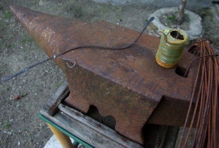
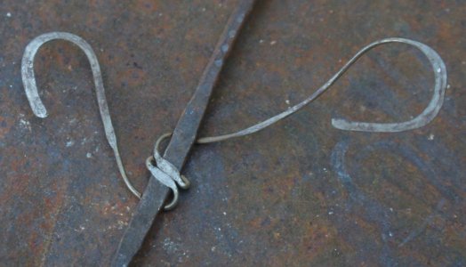
So today I try to hammer some iron wire, and the result wasn't bad at all:

wrought_iron.jpg

The "big" wire is 3 mm thick, while the smaller is the one we use to tie the rebars when making reinforced concrete, 1 mm thick.
To make that curve took me just a couple of minutes, and I'm not at all a skilled blacksmith (the pro anvil is a gift from a friend who don't use it).
It's amazing how much an 1 mm wire can be widened using just a small (0.8 kg) lump hammer!

wrought_iron2.jpg

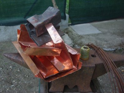
Since the easiest thing to do with wire is something "botanical", one of my neighbors specialized in roof working gave me some scraps of the copper used here for gutters and roof finishings, to be converted in something looking like leaves:

copper.jpg

But leaves will be for another day: I have other things into my todo list, before this.

WARNING: hammering iron makes it REALLY HOT!
(don't ask me how I learned this)

wrought_iron.jpg wrought_iron2.jpg copper.jpg
 
Re: Cold saw

I'm trying to build a cold saw out of parts I had sitting around in the shop. Still need to rig up a switch, guard, and coolant.

Any suggestions?
I have been working in machine shops for 45 years. Worked in shops with machines run from line shafts with flat belts flapping all over the place and guards ripped off machines and piled in the corners.
And I must say, that is the scariest looking machine I have ever seen. :lmao:
You have GOT to post pictures after the guards are in place!

I do have one suggestion, make sure your insurance is up to date!

John

In the first manufacturing plant I worked at there was a 36" Cold saw buried deep in the rear bowels of the steel shop.
When I first saw that monster cutting up structural steel I wasn't sure whether to be awed or scared of/by it.

_Dan
 
POTD Steady Rest for Monarch 14C Lathe

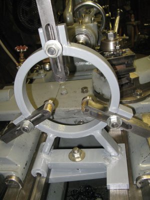
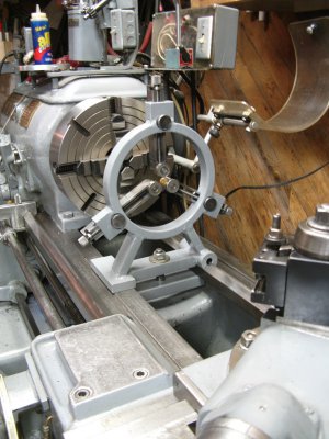
The Monarch needed a steady rest so I put one together with some iron and some ball bearings
salvaged from the scrap yard. It took several days to complete and weighs in at about 40 pounds.
The rollers are removable allowing the use of the brazed on tips if desired. It is easy to set up and
will accept large rod stock or pipe or will neck down to hold something as small as one-quarter
inch diameter. Here's a couple photographs of what it looks like. It involved a lot of machining,
set up and welding.

IMG_0425.JPG IMG_0429.JPG
 
Re: POTD - Get a handle on it & organize

Yesterday's efforts, too tired to post last night.

The old Index has been lacking a right side handle since I bought it. I went through my stock on hand and actually came up with this kludge:
The piece of fuel hose in the pulley groove is great for a good grip. Oak handle, 5/16" carriage bolt with a sleeve.
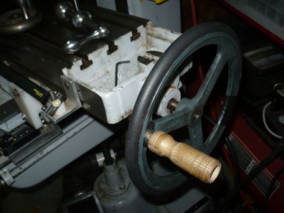
handle_01.jpg

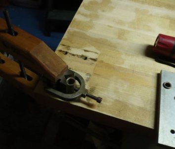
Spot facing backside. Messed up the front side, end mill grabbed. Hence the big ass clamps for working the backside.
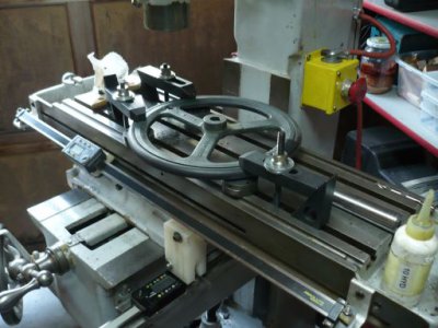
handle_02.jpg

Choice on hand. The regular crank handle was a bit loose with the bushing I have in it, I think it is for a larger machine.
I believe there was something in my coffee when I grab the old pulley that has been floating around for eons.
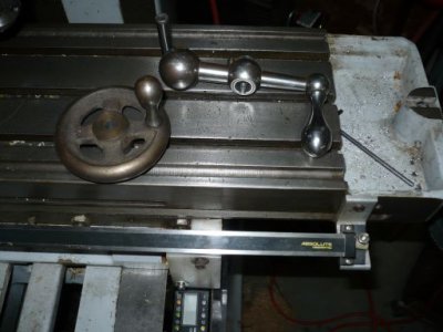
handles.jpg

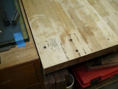
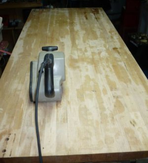
Then on to the 'Bench'. I was lucky & picked this up in a barn find last summer. Looks like it came from an assembly plant.
There was carpet glued on the top and all four sides and it had a uni-strut frame mounted to it supporting a roller rail.
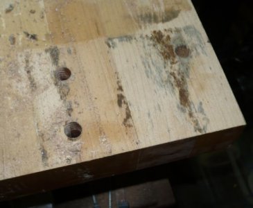
The (6) 3/8" holes were drilled by hand and they weren't straight at all. I decided to drill them out to 1/2" and plug them.
Then I got imaginative and found a 1/2" drill bushing in a drawer, working wood meets machining fixture....
After drilling the first hole I got smart and hugged the drill close. Brand new cleveland drill dug in fast.
The ribs should heal in a couple of days...

Holes before:
butcher_block_holes_before.jpg

Jig in position:
butcher_block_jig.jpg

Holes after:
butcher_block_holes_after.jpg

The carpet adhesive is turning to goo...
butcher_block_02.jpg

... Need to get back to repairing the Birmingham.
_Dan

handle_01.jpg handle_02.jpg handles.jpg butcher_block_holes_before.jpg butcher_block_jig.jpg butcher_block_02.jpg butcher_block_holes_after.jpg
 
I can relate!

Just put together a 10.5 HP B&S engine for a brush cutter that my bicycle club uses to keep a trail system open. Someone forgot to check the oil and scored the cylinder. I was hoping to bore it myself, but realized in time my skills aren't up to the job. I found a local shop to do the machine work instead.

The engine had been working poorly prior to that. Everyone who used it said the same thing. It would run OK for some period of time that was shorter or longer depending on the outside temperature. Then it would sputter, quit, and resist starting for ~45 minutes. It could be cycled like this several times in a day.

Everyone described it as "overheating", but something odd had to be going on. I replaced the ignition coil on the off chance it had developed an internal crack in the conductor, but was not satisfied this was the problem.

I found a troubleshooting chart on line and started working through it. Under the section relating to fuel problems, the chart suggested blowing through the fuel line connecting the gas tank to the carburetor. There was more resistance than seemed appropriate, so I checked the intake screen inside the tank. It appeared fine. I glanced at the cut off valve and thought ,"Well this can't be it. It's been running for years like this." But it was the next logical step, so I turned the tiny handle 90 degrees and the resistance immediately dropped. A lot.

Every idiot, including myself who had used that machine made the same assumption. The valve had to be open because the engine ran. In reality though, it was either leaking internally, or open just a crack. (To be fair, it was not obvious from the way the valve was constructed whether it was open or closed.)

It remains to be seen if opening the fuel cut off valve fixes the "overheating" problem, but I'm betting it does.

Walt
Gas-air mixture ratios does affect exhaust gas temperature, that is why we pilots, adjust mix on airplanes to maintain EGT between correct levels. You mentioned " it has been running like this for years", well several factors will worsten the problem...imagine we have a hot and dry day, also, our carburator is adjusted lean, and by wear, my spark plug gap is wide....also my ignition is just a bit retarded...also by cam wear, then impendance in the cables is high and to make everything worst...the octane on fuel, which has been sitting at the gas station for weeks is a bit low... Add all that and that engine will run hot. Open the jets a little, close the spark plug to minimums, raise the carburator gas level by bending the floater lid, advence the time 2 degrees and change the spark plug cables...change for a colder spark plug...the height of electrode in the spark plug determines the heat range. Hope this helps to unveil the secrets of mixtures....oh, if you can by any means add water spray near the admission, you will find some smooth power. Greetings from Mexico.
 
I finally got boxes done to organize my taps and dies. I had them stored in a big flat drawer but I didn't like them banging together and hated having to search for sizes. I do have a set for larger sizes but never can afford a nice set of smaller ones. I usually buy what I need when I need it and I get lots from junk sales so I have lots of ones in the same size and not every size.

<....................>

The boxes are old Cd cases the local Library was tossing out. The liners are .75" blue foam I cut with a CNC router to match each size. The end labels have the thread size, major dia., Minor Dia., tap drill at 50% and 75% and clearance drill size. I already need to build another rack to start metric taps.

Jeff

Now those you should market. Custom cut blue foam - that is neat.
Mine are banging around in two drawers.
I think that if I had any sort of CNC, I'd spend all my time making organizers and drawer inserts.

_Dan
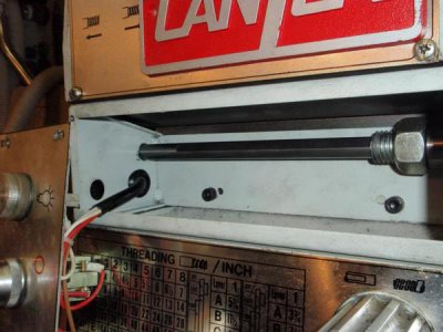
 
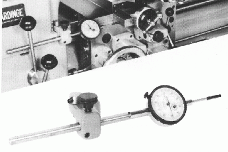
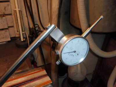
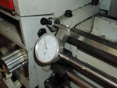
I find myself using a dial indicator quite often to measure carriage travel on my CT1440G lathe. I saw a picture of a Hardinge lathe with the optional carriage travel dial indicator attachment installed and decided to try and make something similar for my machine.

Hardingedialindicator_zps15b82223.gif


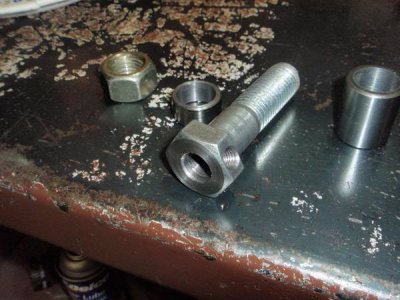
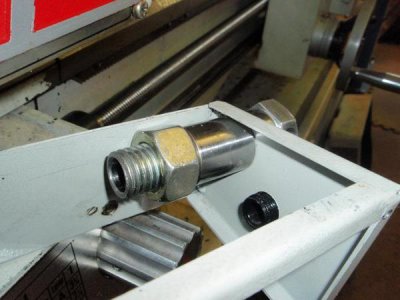
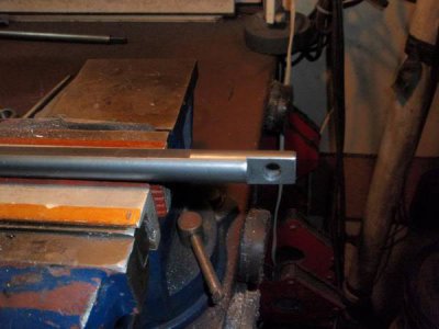
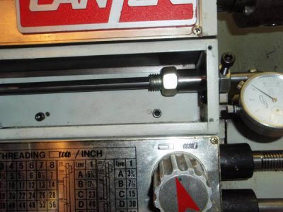
With no convenient place to mount anything to the front of the gear box or switch box I decided to make use of the empty space inside the switch box. I used a length of 1/2" cold rolled for the shaft, a 3/4" by 3.5" bolt for the mount and an old diesel engine wrist pin for spacers. I faced off the bolt and drilled it lengthwise then reamed it to .502" for a nice sliding fit for the 1/2" rod. Then I bored the inside of the wrist pin to fit over the 3/4" bolt to use as spacers. Even though the outside of the wrist pin is very hard, the inside was easy to machine with a carbide boring bar insert. I drilled and tapped one flat of the bolt head for an 8mm set screw.

P5050040_zpsf34d7c59.jpg

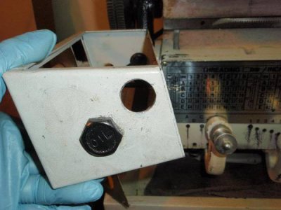
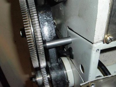
I drilled a 3/4" hole in the thick sheet metal of the switch box to fit the bolt, then mounted the assembly into the upper rear area of the switch box. After I was sure the alignment was good I used the pointed end of the 1/2" rod the mark the other end of the switch box and drilled a hole on that end so the rod can pass all the way through the give me the most amount of travel of the dial indicator possible.

P5050041_zps64f99b97.jpg

P5050043_zps6dc45092.jpg

P5050044_zpsce8622f6.jpg

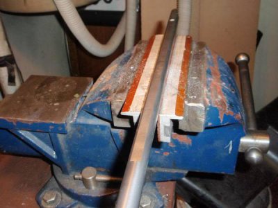
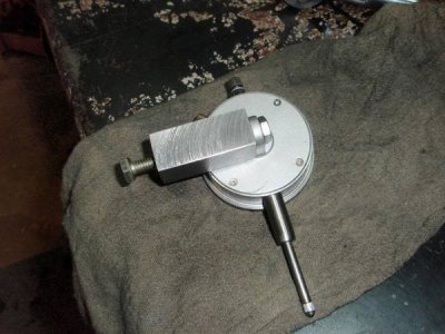
I milled some flats onto the rod so I could mount a piece of 3/4" steel for the dial indicator mount. Then I milled a long flat for the set screw that controls the length of the shaft to seat on. I drilled and tapped the rectangular piece on both ends to hold the dial indicator and to mount it to the rod.

P5050046_zpsef105c4e.jpg

P5050047_zpsfa0d2d1b.jpg

P5050048_zpsab18e862.jpg

P5050049_zpsa2286931.jpg

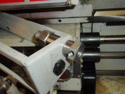
The rod is long enough to give maximum travel but not long enough to contact the gear train when fully retracted. If I need to move the carriage really close to the chuck it can be removed easily. The rod can be extended out to about 14" to measure travel anywhere along that length.

P5050051_zpsc9bd462b.jpg

P5050055_zps1cc68a39.jpg

P5050054_zps29dde627.jpg

P5050052_zps64627127.jpg


P5050056_zps69517816.jpg
 
Back
Top