2016 POTD Thread Archive

If you can drill through, then you could just hold it in the vice or clamped to the T-slot. Tap the first side, flip it over then use the drill bit to align for the other side.

Great idea and thanks. Why didn't I think of that ..... just trying to make things way too complicated I guess. :)

I don't believe that the keeper have to be exactly 180º apart. More critical is the distance from the hole center to the end face. I measured .258" or 6.55mm on my 602 back plate. You could mark that distance fairly accurately using the lathe. Set your compound up at 0º and with the ER40 chuck off, touch off on the face register of the spindle. Set your dial at zero and back the compound off .258" (if your lathe is like the Grizzly, reading inches from a metric screw, you will have to add .004" for the English/metric approximation). Back the cross feed off and install the ER chuck and lightly scribe marks on your chuck. To get the 180º spacing you can put two marks next to the teeth on the spindle gear, 20 teeth apart and tape a temporary index pointer on the headstock. Align the first tooth with the index mark and scribe a horizontal line with the tool mounted on the compound. Back off and rotate to the second tooth and scribe that line. You should now have your centers for the keeper holes.

Thanks for the information and approach. I roughly measured mine at 0.25 and was going to use that for the offset and not measure it accurately. But I like your method and will definitely use that to mark the offset. I'm also going to try using the spindle gear method of marking the 180's. This could be handy for future reference to use as a dividing method.

Learning something every time I come to this forum. :applause 2:
 
A couple of days before I could finish it (damn shopping)
Proof of concept, it works, faced off some 54mm dia steel bar.
It took a bit of time to centre it correctly so it didnt walk out the chuck.

View attachment 76391

The reason for this steady was for some large dia aluminium I will be machining soon and wanted the bearings to prevent the brass fingers from marking the surface of the aluminium.
The bearings marked the steel so I'm unsure what will happen to the aluminium, but, you cannot feel these marks, maybe its just polish.

View attachment 76392

View attachment 76391 View attachment 76392

G'day Savarin, Nice steady, I'm thinking I might have to make something like that, I have a project coming up that I 'm pretty sure will not fit in the steady on my lathe, The job is about 200mm long and 100mm dia. I like the use of ball bearings as supports, but also concerned about them not being perfectly lined up, have you solved that problem yet?
 
Last edited:
Gas-air mixture ratios does affect exhaust gas temperature, that is why we pilots, adjust mix on airplanes to maintain EGT between correct levels. You mentioned " it has been running like this for years", well several factors will worsten the problem...imagine we have a hot and dry day, also, our carburator is adjusted lean, and by wear, my spark plug gap is wide....also my ignition is just a bit retarded...also by cam wear, then impendance in the cables is high and to make everything worst...the octane on fuel, which has been sitting at the gas station for weeks is a bit low... Add all that and that engine will run hot. Open the jets a little, close the spark plug to minimums, raise the carburator gas level by bending the floater lid, advence the time 2 degrees and change the spark plug cables...change for a colder spark plug...the height of electrode in the spark plug determines the heat range. Hope this helps to unveil the secrets of mixtures....oh, if you can by any means add water spray near the admission, you will find some smooth power. Greetings from Mexico.

Water spray, love it, also known as water injection, although it's not really injected usually just atomised in the carby along with fuel. I have used it on a car with great success. Cooler running motor with heaps more power I found between 10 to 15 parts of fuel to 1 of water worked best.
 
Last edited:
G'day Savarin, Nice steady, I'm thinking I might have to make something like that, I have a project coming up that I 'm pretty sure will not fit in the steady on my lathe, The job is about 200mm long and 100mm dia. I like the use of ball bearings as supports, but also concerned about them not being perfectly lined up, have you solved that problem yet?
I've moved away from the bearings because on a large dia steel bar they disintegrated so I moved over to oil soaked hard wood shoes.
http://www.hobby-machinist.com/threads/80mm-long-focal-length-refractor.26212/page-2 message 47
For the aluminium tubes they worked very well.
I will eventually make new fingers using larger single bearings.
 
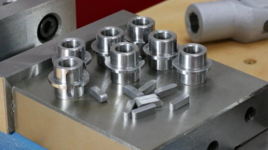
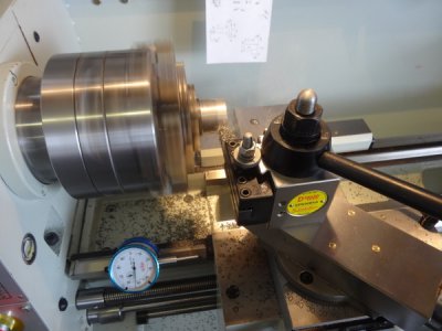
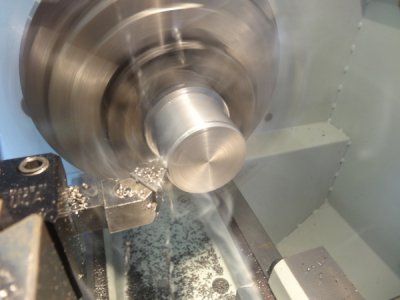
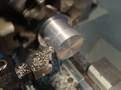
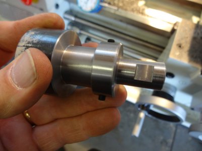
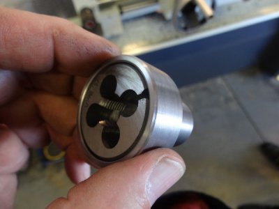
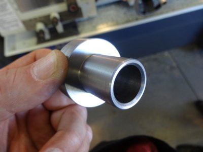
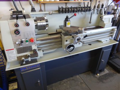
Not sure if I am posting in the correct place, if not then I apologize. This is not what I did in the shop today but a few days earlier. I can't seem to find the time to do everything I would like to do. I enjoy reading the articles and especially seeing pictures of what everyone does so I'm trying to repay by posting some pictures of what I do. I'm not a machinist but have done machine work part time for about 30 years. OK now on to the project----I do some machine work for a place that does electrical motor repairs so in the pictures you will see a picture of the end of an electrical motor that once used a bushing to support the shaft and now that bushing is no longer available so I machined the bore where the bushing was and replaced it with a sleeve to fit a bearing. By the time the material cleaned up on the OD it was about .005 undersize so I knurled - maybe not the correct thing to do but it made for a tight fit. Sorry for the long post.


View attachment 79084View attachment 79085View attachment 79086View attachment 79087View attachment 79088

View attachment 79084 View attachment 79085 View attachment 79086 View attachment 79087 View attachment 79088

Knurling an undersize part has been a classic fix for as long as I can remember, there are many other much cruder ways, but these days a lot of unskilled people just use locktite style products.
 
Last night I had some time to kill while waiting for a guy to pick up his bike so I thought I would cross another item off of my list of things to do. I had wanted to make a larger die holder for my tailstock threading die holder for years and never seemed to get around to it. I didn't have one for 1.5" round dies so I grabbed some 1144 round stock out of the rack and cut a 2" long piece of 1.75" diameter off in my new to me Jet 7x12 horizontal bandsaw that I finally refurbished and got up and running.

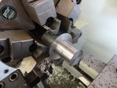
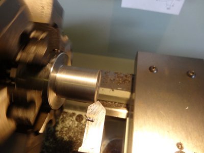
Turning one half down to 1.00" diameter to fit precisely into the smaller die.
2z6ia84.jpg

While machining this part I decided to focus on getting more familiar with my new lathe and seeing just how accurate it is and how repeatable I can make cuts. Like everyone else, once you get a feel for your machine you have a much more precise idea of what kind of roughing cuts you can make and how close to your final dimensions you can get prior to your finishing cut(s).

Here I removed .080" (.040" actual DOC). Machine didn't even flinch. Keep in mind that this is only a 1300 pound/2hp lathe, not one of the 3k pound/5+ HP monsters that some of you guys may have.
33wl3c3.jpg

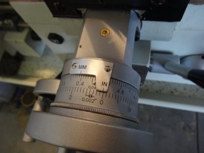
Now I decided to push it a little and take half a dial revolution and measure for accuracy. Here is a .050" DOC, .100 total diameter removal. This dial is taking some getting used to but I am getting much more comfortable with the total diameter markings vs. what I was used to with dial markings signifying crossfeed movement. Prior to this cut I had a measurement of 1.331" and after this cut I had landed at a measurement of 1.229", .002" difference from target to actual.
2d2g4so.jpg

Okay now I decided to take that measurement and make one complete revolution of the crossfeed dial in two consecutive cuts, each cut taking .100" material removal for a total target of .200" material removal. Starting measurement was 1.229" and after one complete dial revolution in two .100" cuts I landed at a measurement of 1.031". Only .002" shy of my target in one revolution of the crossfeed dial, I'll take it. I am completely satisfied with that. Now I am at least getting a very comfortable feeling for the machine to rough out and get within .010"-.020" before taking another measurement and dialing in on the final dimension.
9iyanp.jpg

After measurement I offset my dial to the final dimension and took a final cut of about .014" and faced out.
2lca742.jpg

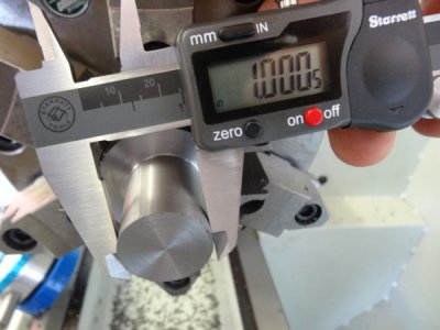
My target was 1.000" and after the final cut of .014" here is my actual dimension. Sorry, I should have grabbed a micrometer for this but was too lazy to walk to the toolbox and get another measuring tool out for something that had some margin. I was more trying to make a target dimension and shoot for it to get a feel for the machine.

Final measurement was 1.0005". Half a thou off from target. Very satisfied.
28wg2p.jpg

Breaking the edge and throwing a chamfer on each of the two sharp edges.
etu0bn.jpg

Test fit into the smaller die holder prior to turning around and machining the other half.
b51y12.jpg

1.5" round thread die drops right in. All I have to do now is drill/tap for my retaining screws.
xp3u5t.jpg

After chamfering the outer edge and the inner bore.
72vnk1.jpg

And after all cleaned up and ready to be put to bed for the evening.
2u3xfet.jpg

Mike.

G'day Mike,

What lathe is that? it looks very similar to mine, although a bit bigger. I have a brand new Laing Dei 1216. It is installed in my workshop, but not yet fully set up, and I'm still acquiring tooling.

I'll be starting on some projects soon and will be posting pics.
 
While grinding my ugly welds yesterday (see welder maintenance issues mentioned previously) my cheap Ryobi angle grinder caught fire, shooting flames out of the end, between the power cord and strain relief. I've known the bearings were in sorry shape since I bought it used for $15 over two years ago. I definitely got my money's worth. :) I suspect the strain of working against the rough bearings was overloading the wiring.

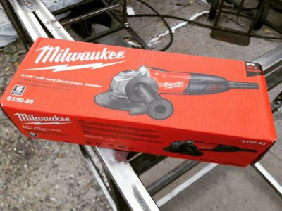
Other than creating a huge delay because I realized while at Home Depot that I had somehow left my debit card in my wife's car, and she was at her mother's house, and when she finally made it she wanted to go grocery shopping while we were already out and... I ended the day with a much nicer Milwaukee grinder. :)

But you know what's annoying? The Ryobi grinder of comparable nominal power has a MUCH more comfortable grip, and the grip rotates to three different positions. That is awesome! But you can feel the difference in the bearings between it and the Milwaukee right there on display, and the Ryobi was already leaking lubricant from three different joints. Not impressive. Why can't I get that cool grip in a Milwaukee? They're the same company! The quick angle change on the blade guard of the Milwaukee is awesome, and overrides the grip question.

eb65c0046b55dd91b3466104f5944793.jpg

06ffa02de7b432e32f06f408fcf3875e.jpg

Same issue with my Ryobi Impact driver, which has a very cool chuck which ejects the bit when you pull it, and it stays open until you insert another bit, so you can do one-handed bit changes. Neither my Milwaukee nor any other I've ever seen has that. Why not? :(
 
Hope you didn't get burned or set something on fire.

I've got an old (maybe 15 or 20 years) Makita angle grinder. I think it is a 4 1/2" and that thing is still going strong. That one was made in Japan. I've had to repair the wire connections at both ends of the cord but it still keeps working and I don't want to replace it because the newer stuff is no where near the same quality. A couple of years ago I decided to get it's bigger brother and got the 7" angle grinder. Every time I use it there are weird smells coming from it and it gets hot. I don't think that will last very long and tend to use the smaller one most often because of that.
 
Back
Top