2017 POTD Thread Archive

Spent the day running my home made firewood processor. Got a little carried away and the back pile grew to 6 feet high. The blocks are pretty much all red oak 24 inches long for the boiler. One more day and this load of logs will be cut. Still have 2 more to do.
FN15yCUar6np40kQtOaQDYQpVqOKRS11AkVhbd4Q8jOUC9zfR7wr_aQwfQ-oAmb1KTDnYtMnJQM3NzDfiuLwxooaoGrjSYdAhdSL2SiNjQb05r5o2ad9rYQUZC_FlNS3Hh2YaI5olyi3TPP3B2U344jDr23qJZie1cA6yGShpK7WqUJX5z-_3IqGnuz4LI590mqip1-Bd1aApxezn7yRzocRSzFqRQa77N0oUKnSzR3AV_ddGheq4valrJw-xxNz0S3ceRvEbYmgsFb9Ydi-eIekerhZItYhpZL2iTktSuLcKBWNIxRrbo1hxRG51s_6v3-A6Wh--zkLtR3SFOjWDME63wfoKRxCFyjEVo1FYRN0V-S-MrEXOPxjWX2u5I0NEd5HayDdXRHwIr4HjcQw2C2fgfRMnK6WVPD7OKJE2U5wyZph368nIZa7Q3zsQV6Xqa4h9BrKZ2tinhwsJN-9JVttNxX_DgrDi5zuMtpLcoVekfdJftMA9t8wtTIMn5TnWn43HGiErs2t9oWqyX2pNiFkes9UF2zkK1Kt1YBIsds3cj0pijplBe2ysuWSz4BZiQ8-mml7-54JSNSuE8avDdh2eH_aF82RTLnhGmBWyDfMF0E6rJJl=w1702-h1276-no


Greg
 
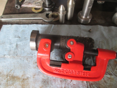
What can you make from a Harbor Freight #2 pipe cutter and a 1.5 inch grade 8 bolt? o_O

upload_2017-9-7_16-21-56.png

Well........ in this case a rotary swaging tool. I need to anchor a 1.25 OD slug into a piece of 1.5 OD x 0.125 wall aluminum tubing. For a couple reasons I can't pin it and I don't trust gluing it in for this application, welding takes too much time in production.. So swaging seems like a good and quick solution.

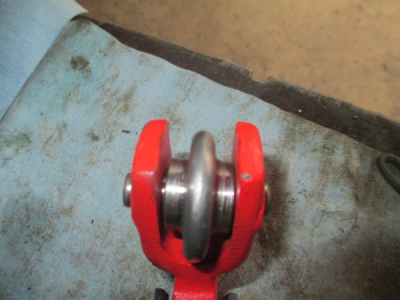
So first replace the cutter wheel with a roundover wheel.
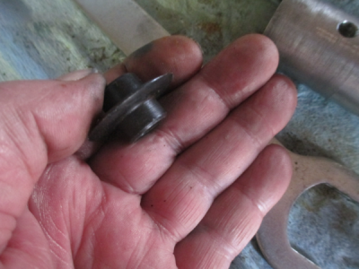
upload_2017-9-7_16-49-11.png

This is where the 1.5 inch bolt comes in. Needed a piece of reasonably hard steel and I had that bolt kicking around. Needs to be 1.375 dia, so turn down the bolt and create the .125 radius profile. A carbide router roundover bit works well for this.
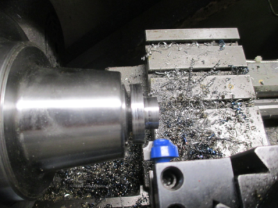
upload_2017-9-7_16-50-6.png

Then drill and ream 0.376 for the new pin. Drill & ream the pipe cutter frame at 0.3745 to get a good press fit on the 0.375 dowel pin

Lining up the on original hole as best I can with with a drill bit that was a snug fit in the hole.
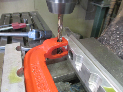
upload_2017-9-7_16-54-23.png

And the new wheel installed
upload_2017-9-7_16-59-44.png

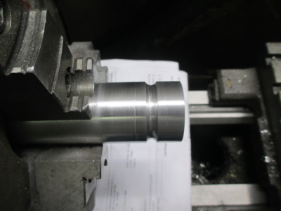
First cut a radius on the slug, then mark the location on the tube.
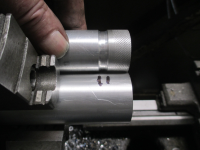
upload_2017-9-7_17-1-0.png

Turn on the lathe at 70 RPM, and crank on the handle.
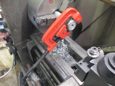
upload_2017-9-7_17-8-28.png

And the swaged test part completed. Went a bit too deep on this one, but still learning how to use the tool.:confused:
upload_2017-9-7_17-10-18.png

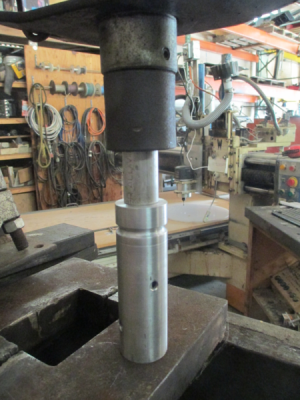
So now it's time for a little destructive testing. Took 10 tons to press the slug out of the tube. In use, the maximum load on the swaged joint might be as much as about 200 lbs. I'll do a double swage on the production parts just for redundant redundancy.;)

upload_2017-9-7_17-22-53.png

And this is how it looks after pressing out. Sheared the swaged over area inside the tube. Looks like the radius in the slug needs to be a bit wider. Need to do a few more test parts to determine the best combination and get a good fit up.
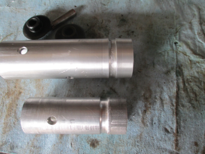
upload_2017-9-7_17-18-59.png


Over all it looks like a success :)
 
Now this is where I need some advice.
To bore the next two holes I worried about my marking out and whether it was accurate enough so I decided to sneak up on their diameters until the gap measured the same on all three gaps.
Do you think this as the right way to go?
I'm going to differ with TomS's post. I don't think the three holes need to be very exactly positioned. Recall that, geometrically, three points define a circle. So the three jaws of the chuck will "find" the three holes (actually the six points where the center hole intersects the outer holes) and "define" the geometry accordingly. The center hole (and the periphery of the disk) may not be exactly lined up with the center of spindle rotation, but the edges of the center hole will be way outside where you're grinding. So it shouldn't matter.

Hope I'm not missing something.

I'm not following your logic that three points define a circle. What if you have three points in line. How does that define a circle. Please educate me.
 
I'm not following your logic that three points define a circle. What if you have three points in line. How does that define a circle. Please educate me.

Three points on a straight line defines a circle of infinite radius.

If you accept that explanation, consider yourself educated. :grin:
 
The three jaw holes need to be on the same radius, exactly 120 deg arcs, and the same size. Difficult to do using the method you describe, but possible. Why not just make a heavy wall ring then chuck it in your three jaw and grind the jaws?

I understand your argument but, it assumes that the chuck jaws are exactly 120° apart and each jaw is equally chamfered.

A gage quality jaw plate would be ideal to go with a gage quality chuck.

Real world compromises being more common . . .
 
John, the problem is that there are six points. If the six points of contact are not on the same circle, it could bias the jaws. For example, if one of the hole centers was further out than the other two , the other jaws would not be hitting on both points. Same if the the holes were not 120º apart. If the jaws are tight in their t slot, the effect wouldn't be too great but if there is any play the grinding operation could be distorted. When the reground chuck is then used, it wouldn't be gripping on a circle.
 
we wont find out for a while because I snapped a tap (I'm a master at doing this) in the die grinder holder I was making.
 
I'm going to differ with TomS's post. I don't think the three holes need to be very exactly positioned. Recall that, geometrically, three points define a circle. So the three jaws of the chuck will "find" the three holes (actually the six points where the center hole intersects the outer holes) and "define" the geometry accordingly. The center hole (and the periphery of the disk) may not be exactly lined up with the center of spindle rotation, but the edges of the center hole will be way outside where you're grinding. So it shouldn't matter.

I agree with the above very well explained theory of operation. I have made several of these plates from 1/2" aluminum for both a 3 jaw 6" and 8" chucks and a four holer for a 6" universal 4 jaw chuck. I ground each chuck to have less than .001" runout. As explained in the quote the unit is self centering, even on the four jaw chuck. As well the plate is held with significant clamping force equal to holding a piece of stock. The jaws will bite into and deform the aluminum to gain equilibrium in pressure so that the grind is very accurate. The plate clamps or holds the jaws at roughly their center point, unlike a ring which holds the jaws at their innermost end which might not place the jaw surfaces parallel to the centerline. If the jaws are loose in the chuck with side play, grinding will only help to a certain extent since the position of the jaws will change each time an item is clamped for machining.
 
Back
Top