-
Welcome back Guest! Did you know you can mentor other members here at H-M? If not, please check out our Relaunch of Hobby Machinist Mentoring Program!
You are using an out of date browser. It may not display this or other websites correctly.
You should upgrade or use an alternative browser.
You should upgrade or use an alternative browser.
A Dividing Head Anyone Can Build
- Thread starter Mark_f
- Start date
I have written a computer program that solves indexing problems and if desired will print out a chart of solutions for the workshop. Rather than going into long details here check out the web page.
http://www.dogcreek.ca/shopcalc/shopcalc13/index.html
This is my latest version and not yet publicly released (still waiting for Spanish and Dutch translations). This is free software.
I recently downloaded the latest version of shop calc. It was talked about on another forum I was reading. I haven't really looked at it yet, but will go do that now. ........ Rats!..... I went to check it out but it works with a few ratios but not the 30:1 for the dividing head. Oh well, that is my luck.
Thanks,
Mark
- Joined
- Jun 20, 2012
- Messages
- 43
I recently downloaded the latest version of shop calc. It was talked about on another forum I was reading. I haven't really looked at it yet, but will go do that now. ........ Rats!..... I went to check it out but it works with a few ratios but not the 30:1 for the dividing head. Oh well, that is my luck.
Thanks,
Mark
Shopcalc can be customized for 30-1 quite easily. In the same folder as ShopCalc there is "DoNotEditOrDelete.ini" that can be opened in notepad. Scroll down to the very bottom and type in "[30-1]" then press Enter and on the new line type "0=30-1" then press Enter again (it is very important that you press enter after "0=30-1") or you will get an error message.
Now when you start ShopCalc you can select 30-1 and start adding the hole plates that you will use. Obviously I need to provide a method to add a custom ratio. That will take a while as "She who must be obeyed" has me remodeling the bathroom.
Last edited:
Shopcalc can be customized for 30-1 quite easily. In the same folder as ShopCalc there is "DoNotEditOrDelete.ini" that can be opened in notepad. Scroll down to the very bottom and type in "[30-1]" then press Enter and on the new line type "0=30-1" then press Enter again (it is very important that you press enter after "0=30-1") or you will get an error message.
Now when you start ShopCalc you can select 30-1 and start adding the hole plates that you will use. Obviously I need to provide a method to add a custom ratio. That will take a while as "She who must be obeyed" has me remodeling the bathroom.
COOL!! ... thank you very much..... now I can figure my plates much easier.
THANK YOU!
Almost done with the spindle.
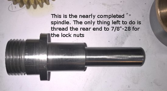 This is the spindle. The only thing left to do is thread the rear end.
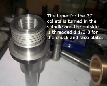 The center of the spindle is bored to accept 3C collets and the outside is threaded 1 1/2-8 to acept a chuck or a face plate or an ER 40 adapter.
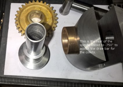 This is the rear of the spindle bored to .750 halfway through to accept the 3C collet draw bar. this was not planned but is not a problem. the rear end wall is .063" thick. Plenty of room for the 7/8"-28 threads on the outside, but no room for a key for the gear, so I will be using two grub set screws 90 degrees apart with a slight dimple in the spindle to capture them. All the load is on the front half of the spindle ( 1.250" diameter), so the thinner rear wall is not a problem since it is only support and not really load bearing. There is very little stress in this area. The reason it worked out this way was I wanted to use the gear as it was and not modify it or half to make a new key way. That backfired because now I can't use a key anyway. Ideally, I could have bored the gear out to 1" and had a thicker wall. But it doesn't matter, this is just as good and I am trying to keep things easy and simple so anyone can build this and end up with a good quality tool. Tomorrow .... thread the rear of the spindle and make lock nuts ..... I hope.
 This is the spindle. The only thing left to do is thread the rear end.
 The center of the spindle is bored to accept 3C collets and the outside is threaded 1 1/2-8 to acept a chuck or a face plate or an ER 40 adapter.
 This is the rear of the spindle bored to .750 halfway through to accept the 3C collet draw bar. this was not planned but is not a problem. the rear end wall is .063" thick. Plenty of room for the 7/8"-28 threads on the outside, but no room for a key for the gear, so I will be using two grub set screws 90 degrees apart with a slight dimple in the spindle to capture them. All the load is on the front half of the spindle ( 1.250" diameter), so the thinner rear wall is not a problem since it is only support and not really load bearing. There is very little stress in this area. The reason it worked out this way was I wanted to use the gear as it was and not modify it or half to make a new key way. That backfired because now I can't use a key anyway. Ideally, I could have bored the gear out to 1" and had a thicker wall. But it doesn't matter, this is just as good and I am trying to keep things easy and simple so anyone can build this and end up with a good quality tool. Tomorrow .... thread the rear of the spindle and make lock nuts ..... I hope.
This morning I threaded the rear of the spindle 7/8"-28 and made two lock nuts to put on the rear of the spindle.
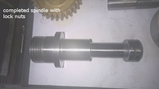 This is the completed spindle. ready to go.
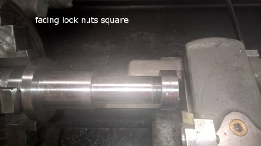 After making the lock nuts, I threaded them on the spindle and face both sides of the lock nuts while on the spindle so they would be perfectly square.
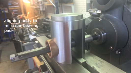 I needed to face a bearing pad on the rear of the body but it had to be square with the spindle bore. To line this up , I put a bushing and a rod in the bore and the other end of the rod in the collet in the mill spindle. this held everything in alignment while I clamped it down for milling.
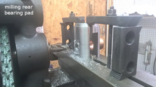 After clamping down the rear bearing pad is milled on the body. this makes a flat surface for the lock nuts ( or bearings, if I use them) to ride against holding the spindle in the body.
 With all that done, it is time to make the other end of the body. A piece of 3 1/8" diameter steel bar stock is turned to size and a trunion bearing surface is turned just like the other body end. Next a slot will be cut for the clearance for the gear.
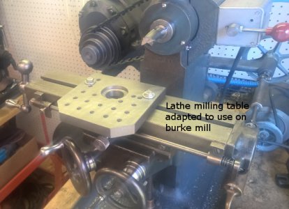 In order to hold this piece on the mill, I adapted my lathe milling table by drilling two 3/8" holes so it can be bolted on the mill table. This worked so well, I think I will make a auxiliary table just for the mill ).
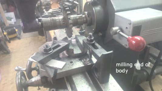 The body end is clamped down and using a .375" wide cutter it was short work to mill the slot. It was almost 3 cutter widths wide and I was taking .200" cuts.
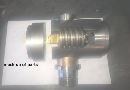
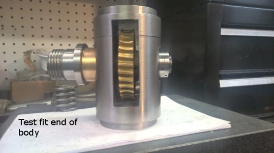 Here is the test fit of the body parts. You probably get the idea of how this works now, but if you don't ,, keep watching .....more tomorrow. I need to drill and bolt these parts together, need oilers installed to oil the bearings, and get started on the base unit.
 This is the completed spindle. ready to go.
 After making the lock nuts, I threaded them on the spindle and face both sides of the lock nuts while on the spindle so they would be perfectly square.
 I needed to face a bearing pad on the rear of the body but it had to be square with the spindle bore. To line this up , I put a bushing and a rod in the bore and the other end of the rod in the collet in the mill spindle. this held everything in alignment while I clamped it down for milling.
 After clamping down the rear bearing pad is milled on the body. this makes a flat surface for the lock nuts ( or bearings, if I use them) to ride against holding the spindle in the body.
 With all that done, it is time to make the other end of the body. A piece of 3 1/8" diameter steel bar stock is turned to size and a trunion bearing surface is turned just like the other body end. Next a slot will be cut for the clearance for the gear.
 In order to hold this piece on the mill, I adapted my lathe milling table by drilling two 3/8" holes so it can be bolted on the mill table. This worked so well, I think I will make a auxiliary table just for the mill ).
  The body end is clamped down and using a .375" wide cutter it was short work to mill the slot. It was almost 3 cutter widths wide and I was taking .200" cuts.
 Here is the test fit of the body parts. You probably get the idea of how this works now, but if you don't ,, keep watching .....more tomorrow. I need to drill and bolt these parts together, need oilers installed to oil the bearings, and get started on the base unit.
today , I finished the body and started the base.
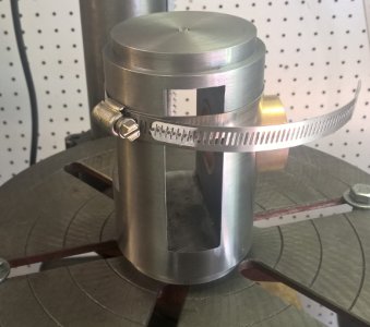 I used a hose clamp to hold the body parts aligned while I drilled for bolts and pins to hold it together.
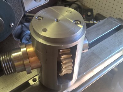 After drilling, tapping , and reaming, the body is finished with two 1/4-20 bolts and two .750"alignment pins.
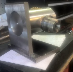 The base will start with a piece of 4" x 6" x 1/2" thick angle iron. I bored a 2.750" hole for the body trunion to fit. I also fly cut the back square with the bottom and will fly cut the bottom flat.
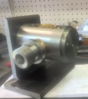 Another view of how the body and base will go together. I am making end caps for the trunions that will clamp with two bolts. when loosened the spindle can be rotated to the vertical position or anywhere in between.
 I used a hose clamp to hold the body parts aligned while I drilled for bolts and pins to hold it together.
 After drilling, tapping , and reaming, the body is finished with two 1/4-20 bolts and two .750"alignment pins.
 The base will start with a piece of 4" x 6" x 1/2" thick angle iron. I bored a 2.750" hole for the body trunion to fit. I also fly cut the back square with the bottom and will fly cut the bottom flat.
 Another view of how the body and base will go together. I am making end caps for the trunions that will clamp with two bolts. when loosened the spindle can be rotated to the vertical position or anywhere in between.
- Joined
- Feb 7, 2014
- Messages
- 350
I realize that you are way down the rabbit hole now, but - If the body was larger in diameter, then you could rotate the the head on the worm axis, rather than the spindle axis. That way the plates, sectors, handle, and all would stay in the same place when the head was rotated from horizontal to vertical.
Larry
Larry
