I make mistakes, sometimes big and sometimes small. When I put the graduations on ,I put them on and realized they were on the bottom, so I did a second set on the top. No one will ever see them unless they look at the under side.I never cease to be impressed by your work Mark! Whatever mistakes you make your projects always end up looking like professionally made pieces
-
Welcome back Guest! Did you know you can mentor other members here at H-M? If not, please check out our Relaunch of Hobby Machinist Mentoring Program!
You are using an out of date browser. It may not display this or other websites correctly.
You should upgrade or use an alternative browser.
You should upgrade or use an alternative browser.
A Dividing Head Anyone Can Build
- Thread starter Mark_f
- Start date
And the winner is ..... BLACK WRINKLE FINISH. I painted the first part today and chose the black wrinkle finish because it looks expensive and is durable.
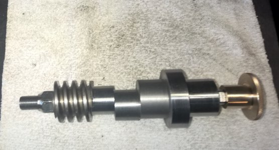
I spent a lot of time figuring out the worm setup to get everything I wanted. This photo is the complete worm assembly. I had to make the eccentric and the hub to hold the index plates in two pieces and lock-tite them together . I cut the flats on the end of the shaft to hold the index handle and made a pretty brass hand wheel to hold the index handle on. I wanted it easy to remove to change plates. I also threaded the shaft and put a lock nut to hold the worm on.
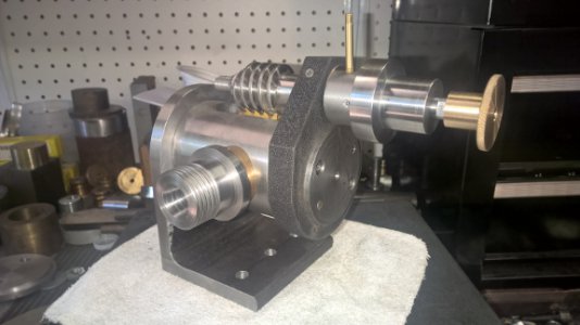 This is the assembly of what is done so far. The worm mounting plate is painted and mounted. I should not have to disassemble it from the body anymore. There is a set screw in the back side to lock it to the body. It is also a kind of press fit on, so it will not move. it rotates with the body to go to the vertical position. You can also see the fancy brass hand wheel to hold the index handle on. There is a set screw assembly made up of a brass plug and two lock set screws in the front of the plate in the photo. This brass plug provides a little tension on the worm eccentric so it doesn't flop back and forth. It requires a light push to rotate the worm to engage or disengage and it will stay in position until it can be locked. The little 3/16" diameter brass lever sticking up is to engage or disengage the worm by rotating eccentric using this lever. I ordered a nice red knob for it from McMaster Carr. The gears turn very smoothly with almost no detectable back lash ( which is adjustable by the eccentric to be as loose or tight as I want.
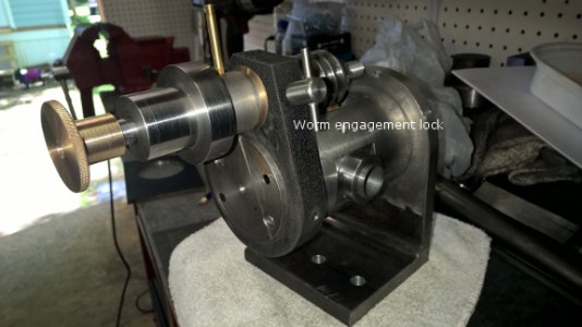 This is a rear view. The "T" handle is the lock to secure the worm eccentric in position. You can see the trunnion sticking through the plate .150". Originally there was not going to be an outboard trunnion and I still believe it is sturdy enough without it, but I am putting one on. It will be a lighter weight assembly made from 1/4" steel plate. By having it , there will be the little extra support and make things that much sturdier and prevent vibration of the body hanging out there.
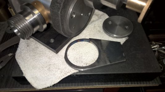 This plate is the outboard trunnion support. It is 1/4" steel plate. due to the close area of the worm mounting, the trunnion ring is not as heavy as the main support on the other end. You can see a narrowed section for 90 degrees that had to be relieved to allow the rotation to the vertical position. This assembly is heavier than it looks. When the ring is captured between the body and end plate, there is a total thickness of 1/2" of steel clamped up. It will provide more than adequate support on this end.
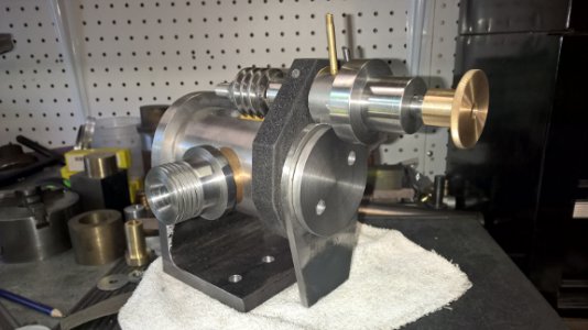 Here the trunnion is mounted. I still have to put the 3/8"-16 bolts in that clamp everything together. There will also be a heavy duty bracket to connect the second trunnion plate to the main base. I still have to drill and tap three 10-24 holes in the plate hub to mount the index plates. This will be done when the plates are made and all drilled at the same time.
In answer to the question asked about a cover for the worm gear to keep swarf out. YES, there will be a cover over the gear. I just haven't designed it yet and it will be one of the last details done. There will be a direct index plate behind the chuck with 24 and 36 holes in it and also marked in degrees. There will be a spring loaded pin to engage this plate when it is in use. I left that flat on the front side of the worm plate to fasten the spindle lock to. Yes, I will need a spindle lock . I also need to make a center and drive dog for working between centers. I have the material for it on hand.
I have tried to put everything in this project that the big honking 200 pound heads have. :
1.) a thirty to one gear ratio which will cover all divisions up to 50 and many others above using a minimum number of holes circles.
2.) 1 1/2"-8 threaded spindle that also accepts 3C collets and utilizes all my lathe chucks and face plates, giving me maximum versatility.
3.) the ability to rotate 90 degrees to the vertical position as well as the horizontal position.
4.) an easy to use eccentric to disengage the worm and allow simple indexing using a plate and spring loaded pin.
5.) A spindle lock to lock the spindle in position.
6.) easy to remove index handle ( no tools needed) and sector arms which will make plate changes simple.
7.) The unit is relatively small but heavy duty and fits nicely on the smaller mills such as the Burke. One person can carry it!
Have I forgotten anything?
I spent a lot of time figuring out the worm setup to get everything I wanted. This photo is the complete worm assembly. I had to make the eccentric and the hub to hold the index plates in two pieces and lock-tite them together . I cut the flats on the end of the shaft to hold the index handle and made a pretty brass hand wheel to hold the index handle on. I wanted it easy to remove to change plates. I also threaded the shaft and put a lock nut to hold the worm on.

 This is the assembly of what is done so far. The worm mounting plate is painted and mounted. I should not have to disassemble it from the body anymore. There is a set screw in the back side to lock it to the body. It is also a kind of press fit on, so it will not move. it rotates with the body to go to the vertical position. You can also see the fancy brass hand wheel to hold the index handle on. There is a set screw assembly made up of a brass plug and two lock set screws in the front of the plate in the photo. This brass plug provides a little tension on the worm eccentric so it doesn't flop back and forth. It requires a light push to rotate the worm to engage or disengage and it will stay in position until it can be locked. The little 3/16" diameter brass lever sticking up is to engage or disengage the worm by rotating eccentric using this lever. I ordered a nice red knob for it from McMaster Carr. The gears turn very smoothly with almost no detectable back lash ( which is adjustable by the eccentric to be as loose or tight as I want.
 This is a rear view. The "T" handle is the lock to secure the worm eccentric in position. You can see the trunnion sticking through the plate .150". Originally there was not going to be an outboard trunnion and I still believe it is sturdy enough without it, but I am putting one on. It will be a lighter weight assembly made from 1/4" steel plate. By having it , there will be the little extra support and make things that much sturdier and prevent vibration of the body hanging out there.
 This plate is the outboard trunnion support. It is 1/4" steel plate. due to the close area of the worm mounting, the trunnion ring is not as heavy as the main support on the other end. You can see a narrowed section for 90 degrees that had to be relieved to allow the rotation to the vertical position. This assembly is heavier than it looks. When the ring is captured between the body and end plate, there is a total thickness of 1/2" of steel clamped up. It will provide more than adequate support on this end.
 Here the trunnion is mounted. I still have to put the 3/8"-16 bolts in that clamp everything together. There will also be a heavy duty bracket to connect the second trunnion plate to the main base. I still have to drill and tap three 10-24 holes in the plate hub to mount the index plates. This will be done when the plates are made and all drilled at the same time.
In answer to the question asked about a cover for the worm gear to keep swarf out. YES, there will be a cover over the gear. I just haven't designed it yet and it will be one of the last details done. There will be a direct index plate behind the chuck with 24 and 36 holes in it and also marked in degrees. There will be a spring loaded pin to engage this plate when it is in use. I left that flat on the front side of the worm plate to fasten the spindle lock to. Yes, I will need a spindle lock . I also need to make a center and drive dog for working between centers. I have the material for it on hand.
I have tried to put everything in this project that the big honking 200 pound heads have. :
1.) a thirty to one gear ratio which will cover all divisions up to 50 and many others above using a minimum number of holes circles.
2.) 1 1/2"-8 threaded spindle that also accepts 3C collets and utilizes all my lathe chucks and face plates, giving me maximum versatility.
3.) the ability to rotate 90 degrees to the vertical position as well as the horizontal position.
4.) an easy to use eccentric to disengage the worm and allow simple indexing using a plate and spring loaded pin.
5.) A spindle lock to lock the spindle in position.
6.) easy to remove index handle ( no tools needed) and sector arms which will make plate changes simple.
7.) The unit is relatively small but heavy duty and fits nicely on the smaller mills such as the Burke. One person can carry it!
Have I forgotten anything?
Last edited by a moderator:
- Joined
- Oct 20, 2014
- Messages
- 495
I can think of only one thing that could make it a little bit better of a tool, and it's a minor thing.
A spring loaded pin in the trunnion that engages holes in the body at commonly used angles, or at least horizontal and vertical. That would make setup or switching a breeze, and intermediate angles could be added to cut things such as bevel gears.
I wouldn't call it a necessary feature, and I'm not even sure if the big dollar heads have that. But it would be handy to just pull the plunger, and rotate the body until the plunger drops in, knowing you'll be perfectly horizontal or vertical. And it's one more item on that that can be shiny.
I can think of only one thing that could make it a little bit better of a tool, and it's a minor thing.
A spring loaded pin in the trunnion that engages holes in the body at commonly used angles, or at least horizontal and vertical. That would make setup or switching a breeze, and intermediate angles could be added to cut things such as bevel gears.
I wouldn't call it a necessary feature, and I'm not even sure if the big dollar heads have that. But it would be handy to just pull the plunger, and rotate the body until the plunger drops in, knowing you'll be perfectly horizontal or vertical. And it's one more item on that that can be shiny.
Ahhhh .... you know I like shiny things.
I had actually thought about that very feature, but didn't do it because I didn't think it would give great precision and I could read the degree scale as good. BUT... after moving the built assembly a few times, I realize this could be a handy item, so I may just go ahead an add it soon.
I am really pleased with the way this project is turning out.
I noticed when assembled the shaft flops back and forth like the button on the outhouse door without the handle and knob installed, so I decided to install an e-clip to keep everything in place.
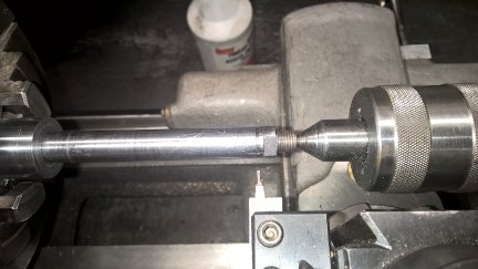 I ground a .046" wide grooving tool to cut the groove for the e-clip.
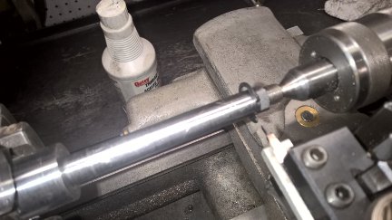 the groove is cut .052" deep per the chart online from the manufacturer and the clip fit perfect.
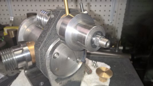 This is the clip installed. It is ALMOST perfect. There is .008" endplay in the shaft. It reall won't matter but I want to cut a brass shim at .007" to remove that slack.
Next I made up a draw bar for the 3C collets.
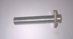 The draw bar has a brass end that has a hand wheel to tighten it with. I will cut wrench flats on the brass stub but have not done that yet. Most of the time, I only hand tighten collets.
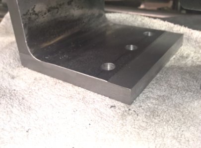 I machined the end of the base flat and square to accept a bolt on extension made from 1" thick steel plate. A step .475" x .500" is cut in the 1 inch plate and it is bolted through and into the end of the base to attach it.
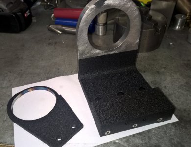 With the extension attached the frame is painted with Black wrinkle finish and it came out really nice.
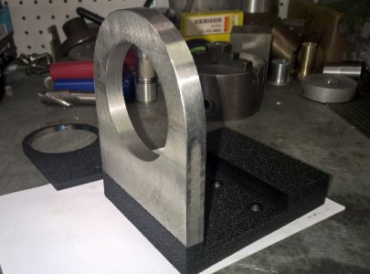 Another view of the painted frame. Now to assemble the head for the last time.
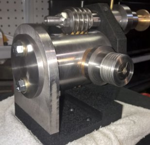 This is a front view of the dividing head assembled. the whole assembly works great. very smooth. i put a collet in the spindle, which reminds me, I need to make a thread protector for the spindle. ( details just keep popping up).
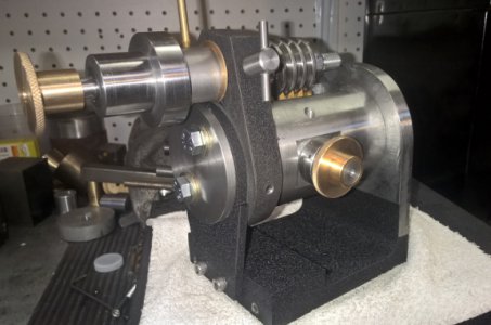 This is a rear view of the dividing head. you can see the draw bar knob that holds the collets in ( I will cut the wrench flats tomorrow). To the left is the set screw locking the worm mounting plate to the body. It was a press fit on , but this will insure it never moves out of place. There is an oil hole to lube the rear spindle bearing above the draw bar in the photo. the "T" handle locks the worm position for engaged or disengaged.
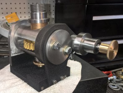 This is the head rotated 90 degrees to the vertical position. The two trunnions are well aligned as the head rotates very smoothly and easily and there is only .005" clearance in the trunnions. I will be using 5 inch index plates so they clear the table when rotated to this position. Six inch plates would work but are close.
So far , I have $50 in making this head and I have the plates, the chuck , the back plate for the chuck, and if I skip buying the brass I want for the handle and sector arms ( which my budget says I may have to do), I have everything to finish this project on hand.
Tomorrow, I start the index plates.
I noticed when assembled the shaft flops back and forth like the button on the outhouse door without the handle and knob installed, so I decided to install an e-clip to keep everything in place.
 I ground a .046" wide grooving tool to cut the groove for the e-clip.
 the groove is cut .052" deep per the chart online from the manufacturer and the clip fit perfect.
 This is the clip installed. It is ALMOST perfect. There is .008" endplay in the shaft. It reall won't matter but I want to cut a brass shim at .007" to remove that slack.
Next I made up a draw bar for the 3C collets.
 The draw bar has a brass end that has a hand wheel to tighten it with. I will cut wrench flats on the brass stub but have not done that yet. Most of the time, I only hand tighten collets.
 I machined the end of the base flat and square to accept a bolt on extension made from 1" thick steel plate. A step .475" x .500" is cut in the 1 inch plate and it is bolted through and into the end of the base to attach it.
 With the extension attached the frame is painted with Black wrinkle finish and it came out really nice.
 Another view of the painted frame. Now to assemble the head for the last time.
 This is a front view of the dividing head assembled. the whole assembly works great. very smooth. i put a collet in the spindle, which reminds me, I need to make a thread protector for the spindle. ( details just keep popping up).
 This is a rear view of the dividing head. you can see the draw bar knob that holds the collets in ( I will cut the wrench flats tomorrow). To the left is the set screw locking the worm mounting plate to the body. It was a press fit on , but this will insure it never moves out of place. There is an oil hole to lube the rear spindle bearing above the draw bar in the photo. the "T" handle locks the worm position for engaged or disengaged.
  This is the head rotated 90 degrees to the vertical position. The two trunnions are well aligned as the head rotates very smoothly and easily and there is only .005" clearance in the trunnions. I will be using 5 inch index plates so they clear the table when rotated to this position. Six inch plates would work but are close.
So far , I have $50 in making this head and I have the plates, the chuck , the back plate for the chuck, and if I skip buying the brass I want for the handle and sector arms ( which my budget says I may have to do), I have everything to finish this project on hand.
Tomorrow, I start the index plates.
Thank you all for the kind words and following the adventures.
I post these projects hoping to show that you all can build the same quality tooling inexpensively... oh the heck with it ...CHEAPLY ... with standard hobbyist machines. I wanted ... and I think most of us would like ... to own a dividing head , but can't lay out hundreds of dollars for one. Yes, I built this on a shoestring budget for about $50 , but buying the material and using scraps it can still be done a LOT cheaper than buying one. Plus there is a lot of satisfaction in using machines and tooling you make yourself.
There is still much left to do on this project, so keep watching and I hope someone is learning from these projects.
Well... I decided to start the index plates. They will be a long and tedious process, especially drilling all those holes. I will make the first set of holes in one plate and the dividing head will make its own hole circles in the plates after that. By doing this, they will be extremely accurate. In fact , i read that if you drill the first set of holes and use them for the head to make the rest from it, the new holes will be 30 times more accurate than the first one you make. So if I take great care to make an accurate set of start holes, the plates resulting will be more accurate than I have the ability to measure. Anyway... on to the work for today.
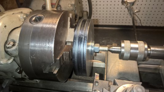 I stacked four 5" round plates 1/4" thick on a 1/2" bolt. After checking several bolts, I found one that spun fairly true, So I center drilled the end and stacked the plates on after drilling a 1/2" hole as close to the center of each as possible. In the photo, my tool is HSS and it wiped out immediately when it hit the torched edges of the plates. I switched to a carbide tool with a fairly large radius and it cut the scale of, then I finished with the HSS tool. The 5 inch plate stack finished a 4.900" diameter. I could have used 6 inch plates and would have but these were available and they will be just fine.
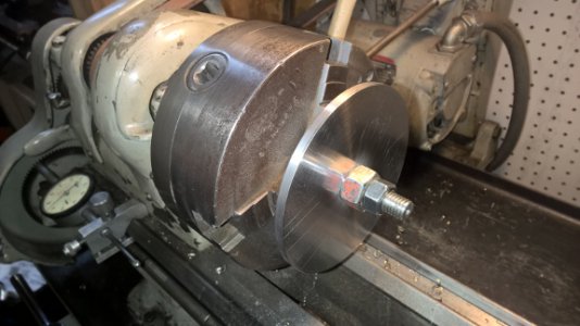 After the plates were trued up, each one was put on the same bolt and the edges smoothed and polished to a nice shiny finish ( I like shiny things
  ). I was going to polish to a mirror finish but figured they are going to scratch up handling and using so i quit at an almost mirror finish ( or very shiny). This head is nice looking, but it ain't a show piece. It WILL get used.
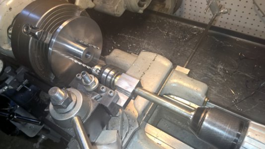 The next step was to mount the hub from the dividing head into the lathe and using my drilling jig I made , drill the three mounting holes in one plate and the hub at the same time. You will notice I put a tight fitting drill in the first finished hole before drilling the second hole. then i put another drill in the second hole before drilling the third hole. This keeps everything aligned. I setup my degree wheel on the back of the lathe to index the 120 degree intervals. I also drilled a 1/8" pin hole, for an alignment pin, between two of the mounting screw holes. This was because no matter how hard I try the holes will not be perfect enough to line up at any position. So the alignment pin will tell where to orient the plate for mounting. I made extremely close tolerance holes. If I oversize the holes I could get them to align in ant position, but I never like doing that, even though the close tolerance hub keeps the plate centered.
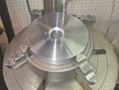 I stacked the plates , in my 4 jaw chuck to hold them on the drill press with the drilled plate on top. If you look close you can see a close fitting sleeve in the center hole to keep all the plates exactly aligned because everything here is very close tolerance and there is no room for errors. The drill follows the hole in the first plate and they will all match and be interchangeable. ( I know this because I tried each one when I finished.
The photo below is the shaft and the first half with the offset and hub which is lock-tited together forever were complicated and took many hours to machine and have all the surfaces a perfect fit. The last thin you want to do is MESS THIS UP. The largest shiny part on the right end is the hub I just drill the three mounting holes in.
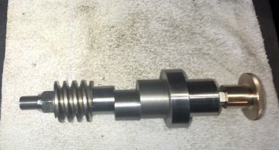
The three holes needed to be tapped 10-24. The first one tapped fairly easy until I got in a ways and it wouldn't go any more. So, I moved to the next hole and it is even harder to tap. So, I try two more new taps and they won't go either. THEN IT HAPPENED! ..... that little "snap"....... the freaking tap broke . and It won't come out. I was envisioning having to make this assembly all over again and I also did not have any material to make it with.
 . I spent the next two hours beating the tap with a punch and hammer and now the hub is all beat and dinged up. Looks like a total loss...
 ... I sat down and thought a bit and with nothing to lose, I put it in the lathe and started hacking at it with a carbide cutter, as I knew it was the only thing I have that will cut a tap. It is a good thing the hub was thick as I had to cut .150: off it to get the tap out. after re machining the banged up areas and some polishing it is as good as new ...
  ...... I so lucky!
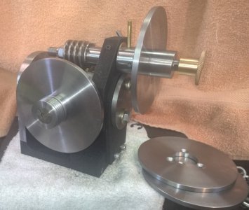 Here is the head with the direct indexing plate and an index plate mounted on the hub. I have three index plates. I plan to mark degree graduations on the outside edge of the direct index plate, but there is no room for the numbers as it is 1/4" thick. I am thinking the numbers , if I put them on could go on the back side at the outer edge .
There was one more thing that was still bugging me. That .009" end play in the worm shaft. I had a piece of brass with a 1/2" hole in it so..... If you want something difficult... try machining a .008" thick washer for a shim. I took a couple tries, but I finally was able to part of a .010" thick one and stuck it to a piece of tape to hold it while I rubbed it on a file until it was .008" thick.
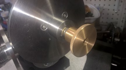 If you look close, you can see my little shim washer behind the e-clip. Now there is virtually no end play in the shaft. With the worm adjusted right this head is really tight, no detectable play and it still turns very smooth. That is what paying close attention too tolerances will do.
The next thing to address probably should be the spindle brake as it will be needed to use the head to make the index plates.
 I stacked four 5" round plates 1/4" thick on a 1/2" bolt. After checking several bolts, I found one that spun fairly true, So I center drilled the end and stacked the plates on after drilling a 1/2" hole as close to the center of each as possible. In the photo, my tool is HSS and it wiped out immediately when it hit the torched edges of the plates. I switched to a carbide tool with a fairly large radius and it cut the scale of, then I finished with the HSS tool. The 5 inch plate stack finished a 4.900" diameter. I could have used 6 inch plates and would have but these were available and they will be just fine.
 After the plates were trued up, each one was put on the same bolt and the edges smoothed and polished to a nice shiny finish ( I like shiny things
  ). I was going to polish to a mirror finish but figured they are going to scratch up handling and using so i quit at an almost mirror finish ( or very shiny). This head is nice looking, but it ain't a show piece. It WILL get used.
 The next step was to mount the hub from the dividing head into the lathe and using my drilling jig I made , drill the three mounting holes in one plate and the hub at the same time. You will notice I put a tight fitting drill in the first finished hole before drilling the second hole. then i put another drill in the second hole before drilling the third hole. This keeps everything aligned. I setup my degree wheel on the back of the lathe to index the 120 degree intervals. I also drilled a 1/8" pin hole, for an alignment pin, between two of the mounting screw holes. This was because no matter how hard I try the holes will not be perfect enough to line up at any position. So the alignment pin will tell where to orient the plate for mounting. I made extremely close tolerance holes. If I oversize the holes I could get them to align in ant position, but I never like doing that, even though the close tolerance hub keeps the plate centered.
 I stacked the plates , in my 4 jaw chuck to hold them on the drill press with the drilled plate on top. If you look close you can see a close fitting sleeve in the center hole to keep all the plates exactly aligned because everything here is very close tolerance and there is no room for errors. The drill follows the hole in the first plate and they will all match and be interchangeable. ( I know this because I tried each one when I finished.
The photo below is the shaft and the first half with the offset and hub which is lock-tited together forever were complicated and took many hours to machine and have all the surfaces a perfect fit. The last thin you want to do is MESS THIS UP. The largest shiny part on the right end is the hub I just drill the three mounting holes in.

The three holes needed to be tapped 10-24. The first one tapped fairly easy until I got in a ways and it wouldn't go any more. So, I moved to the next hole and it is even harder to tap. So, I try two more new taps and they won't go either. THEN IT HAPPENED! ..... that little "snap"....... the freaking tap broke
 . and It won't come out. I was envisioning having to make this assembly all over again and I also did not have any material to make it with.
 ... I sat down and thought a bit and with nothing to lose, I put it in the lathe and started hacking at it with a carbide cutter, as I knew it was the only thing I have that will cut a tap. It is a good thing the hub was thick as I had to cut .150: off it to get the tap out. after re machining the banged up areas and some polishing it is as good as new ...
 Here is the head with the direct indexing plate and an index plate mounted on the hub. I have three index plates. I plan to mark degree graduations on the outside edge of the direct index plate, but there is no room for the numbers as it is 1/4" thick. I am thinking the numbers , if I put them on could go on the back side at the outer edge .
There was one more thing that was still bugging me. That .009" end play in the worm shaft. I had a piece of brass with a 1/2" hole in it so..... If you want something difficult... try machining a .008" thick washer for a shim. I took a couple tries, but I finally was able to part of a .010" thick one and stuck it to a piece of tape to hold it while I rubbed it on a file until it was .008" thick.
 If you look close, you can see my little shim washer behind the e-clip. Now there is virtually no end play in the shaft. With the worm adjusted right this head is really tight, no detectable play and it still turns very smooth. That is what paying close attention too tolerances will do.
The next thing to address probably should be the spindle brake as it will be needed to use the head to make the index plates.
- Joined
- Mar 25, 2013
- Messages
- 5,095
Mark-this is awesome! A great design and it looks great too. I'm not entirely sure this is a dividing head that "anyone" can build. You just have the skills to make it look easy! Nevertheless I may give it a try. But I'm not makin' no 0.008 shims!
R
R
