Battleship Restoration - USS Texas, BB35

You should see the rust where it’s bad! In the lowest decks water has been present for decades. If I heard correctly last week, the shipyard is supposed to remove a lot of that heavy rust, steam clean decks, overheads and bulkheads in the worst areas. The rest will probably be left for volunteers to clean and paint.

There has been so much water in the ship for so long that pretty much all bare steel is rusted. Fortunately there are some things made of bronze and brass. One entire level of the forward tripod was made of bronze to reduce its influence on the magnetic compasses.
 
I was more a lover of aircraft but appreciate ships. In another parallel event I have a buddy in Kingston Canada that told me they just received the last of the Titanic-era steamers to their maritime museum the Keewatin. Quite a ship and have received funds to restore it which the museum has the facilities for. He told me that the Smithsonian had asked if ship was going to be salvaged they wanted the engine. I for one am glad they are not getting their mitts on it as I’d bet it would end up in a warehouse never to be seen again.


Attachments

  • IMG_0598.jpeg
    IMG_0598.jpeg
    362.6 KB · Views: 25
  • IMG_0599.jpeg
    IMG_0599.jpeg
    609.5 KB · Views: 25
When the Keewatin passed through the Welland Canal, the excitement was great. Lots of photos taken!
 
I was more a lover of aircraft but appreciate ships. In another parallel event I have a buddy in Kingston Canada that told me they just received the last of the Titanic-era steamers to their maritime museum the Keewatin. Quite a ship and have received funds to restore it which the museum has the facilities for. He told me that the Smithsonian had asked if ship was going to be salvaged they wanted the engine. I for one am glad they are not getting their mitts on it as I’d bet it would end up in a warehouse never to be seen again.


Thanks for posting the info on the SS Keewatin. Hoping this thread will be a conversation rather than a monologue.

My original reason for wanting machine shop tools was a mix of gunsmithing and building RC airplanes. I built lots of airplanes before I had a mill and lathe but now if a wheel is loose on an axle or I want some other accessory I can make it. I even worked on full sized, mostly aerobatic airplanes for a couple of years. About two years ago while reading up on how various things on battleships worked I discovered that there was an opportunity to volunteer on the Texas. I had visited her with my parents as a child and when in college would just drive out to the ship and look once in a while. Sometimes I bought a ticket and went on board.

The latest is a little tool to cut keyways. I tried one on the lathe but the 3/16" (4.76mm) tool bit used lengthwise was just not stiff enough to cut smoothly and not dig into the workpiece. I made a tool in the style of Clough42's broaching tool to use on my manual lathe.

Since the only steel on hand in an appropriate size was hardware store soft steel and 1/2" 12L14 the tool was made from 12L14 with a HSS bit. The tool requires quite a few operations but it was very easy; probably didn't take more than an hour to make it. I started by polishing about 4-1/2" of the stock before cutting off 4". That was a lot easier than polishing after making. The only hard part was figuring out the geometry so that it would cut without digging in and would cut smoothly. The bore of the gears is 7/8" (22.225mm) so a piece of HSS was cut off at 3/4" (19mm). To get started I ground the cutting surface and clearance on my bench belt sander but that, not surprisingly, was not very square.

Wanting to work with what was on hand I chucked up a Dremel stone in the mill and set the belts for the fastest speed of 2080 rpm. Not much chance of overspeeding a Dremel stone on a milling machine. I first re-ground the relief angle and then the cutting face with that little stone. I tried to keep the DOC increment to .00025" to .0005" (.006mm-.013mm) More aggressive cuts just chewed up the stone. Some blue Sharpie was applied so it was easier to see when the surfaces had been fully cut. On the first try the cutting edge was too aggressive. It kept digging into the test piece of brass which I had bored to the same 7/8" bore as the bronze gears. The ultimate solution was to use a 300 grit diamond stone that I use for woodworking chisels to flatten the tip of the cutting edge. The cutting edge was positioned over the large flat portion of the milling vise and the diamond stone was laid on that surface to keep it parallel. I lowered the cutting tool onto the diamond stone with the manual fine feed while sliding the oiled stone side to side. That took just enough of the sharp bite out of the tool to allow for a DOC of about .005" (.13mm). I found that a little more DOC was better than too shallow, within a narrow range. Too shallow tended to chatter more than a medium cut. The cutting pressure required was surprisingly low and it tool very little time to shave away a ~3/32" keyway. There is a drilled hole just before then end of the slot in the tool. That was originally the end of the slot but I found the resistance to clamping to be too great. The hole has a secondary purpose to insert a 3/32" wire or drill bit to align the cutter square to the work. When it comes time to cut the keyways I'll set up my super spacer so I can accurately cut two slots 180° apart.
 

Attachments

  • IMG_5841.JPG
    IMG_5841.JPG
    384.3 KB · Views: 15
  • IMG_5842.JPG
    IMG_5842.JPG
    426.2 KB · Views: 15
  • IMG_5846.JPG
    IMG_5846.JPG
    248 KB · Views: 15
Hoping this thread will be a conversation rather than a monologue.
<whew> glad to hear that! I have a tendency to swap rabbit holes when life presents a parallel and that was just too weird that while I was reading your thread on USS Texas and I get this email on the SS Keewatin. Just had to post.

After I graduated aircraft school there were no jobs that paid more than what I was making as a car mechanic. But Castle AFB was just down the road and they had a great museum and were always looking for volunteers. I applied and could have gotten on but my schedule and having two little kids there was just no time. I always regretted that.

I have done lots of internal keyways but always with broaches and make guides on the lathe. I also have an Atlas shaper and want to someday to an internal keyway on it. It is so satisfying to actually make something that was always beyond me without a lathe and mill.

Good job on the broaching tool.
 
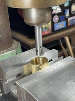
We’ve had a big push to get the 5” guns ready to go back onto the ship. I’ll post pictures first chance. They’ve kept me busy with small jobs. I’ve ended up cutting keyways in 4 of the bronze gears and just brought more of the same home.

Sometimes my alligator mouth gets the better of my parakeet back side. I had another of those moments a couple of weeks ago. One of the staff had a shaft that was part of the training gear (rotation) of a 5” mount that was badly pitted under its bronze bushing. I had never shrink fit parts before but told them, “Sure, I can fix that.” After all, I knew what was required and felt lil it was within my skill level. I got them to order 6” of 1-3/8” annealed 4140.

The little end of the shaft was 1” OD. I really appreciate that engineers in 1910 were inclined to use common dimensions. Most of what I’ve worked on for the battleship has been common Imperial standard sized on 1/4” and occasionally 1/8” increments. That said, the shaft is a few inches longer than the centers distance of my lathe. So grateful that I got a set of ER40 collets and a chuck recently. The outboard end of the shaft for about 8” had a big keyway so I put the stead rest inboard of that area. Fortunately, the other place where the shaft rides in a bronze bushing was undamaged and appeared to be its original diameter. I put indicators on the top and near side of the shaft and was pleased to get it aligned within a couple of tenths over 8”-10”. The speeds and feeds calculator called for at least 1200 rpm. The metal cut beautifully but showered me with really hot chips. It took about 0.100” to remove all of the pitting. The final OD was 1.043”.

I cut off 2-3/4” of the 4140 and started boring with drills and then boring bars until it hit 1.042”. A test fit confirmed an interference fit. A propane torch was enough to get the 4140 blue hot. The sleeve dropped onto the shaft like I knew what I was doing with a nice clink. It was given a little time to cool and then turned down to match the diameter of the undamaged area. The final .0005” was taken off with a big file and emery cloth. After that I machined about 0.1” of excess off of the end, set it up in the mill and recut the keyway slots into the sleeve. Leaving the turned down area a little over 1.000” made it easy to get the correct length and eliminated the need to touch the original 1” area with cutting tools.

Upon test fitting it passed through the first bushing but was tight in the second, where it runs. After a quick pass in the bore with a hone it fit slop free.
 
The battleship's hull has been painted in the Measure 21 scheme as she was at the end of WWII. The bulges on the sides of the hull are torpedo blisters which had to be cut away and completely new blisters were fabricated. The expected re-launch date is sometime in February.

2023-12-30 New Paint on BB35 Photo by Fred Easter.jpg2024-01-15 photo by David Parker.JPG
 
Here are some more little things I've done for the restoration. First are some "pretty close" reproductions of some end caps. Only the outside edge is visible so they told me not to go overboard reproducing the curves on the original. The next picture is of a sleeve being removed from a 5" gun barrel. The bare barrel is 10,770 pounds and the sleeve is about 3,500 pounds.

The hunk of rusty metal is part of the sight system for the 5" gun mount. The trapezoid piece was rusted into the main casting but surprisingly, with a little Kroil, the screw came out pretty easily. considering it had possibly as much as 112 years of exposure to the weather and salt spray. The last photo is of the setup to machine a new screw. The screws are 1-1/8" x 7 tpi left hand threads and a little over 18" long. A 36" piece in carbon steel was about $198.00 and they had to buy 3 of them. I machined a piece of mystery steel to make the sleeve. It's a tight slip fit and the stainless 8-32 screws just keep it from slipping. It might have originally been a stud used to attach the two sides of a gas turbine together since it came out of a scrap bin at an electricity generating company's dumpster. The overall size after cleaning it up and removing the threads was about 1.5"x9". It was rusty but machines very stringy and will work harden in a heartbeat like stainless. The pressure is substantial to not make a mistake.IMG_6004.JPGIMG_6008.JPGIMG_5980.JPGIMG_6026.JPG
 
David, I think your work on the Texas is close to a dream hobby job. Thanks for the pictures of what you are doing. Wish I was closer to Galveston.
 
Back
Top